


When fire alarm control panels need to exchange information across buildings, whether a CAN fiber optic transceiver can be used first depends on the networking interface the panel actually provides and the connection methods the manufacturer permits. The CAN fiber optic transceiver handles the fiber optic remote transmission of the corresponding CAN communication; it does not replace the alarm panel in judging fire, and it will not automatically translate different brands’ proprietary protocols into mutually compatible languages. The plan must simultaneously check the interface, transmission behavior, and event handling, and then be confirmed and verified by the party responsible for the system. You cannot conclude that alarm networking is qualified just because the optical port light is on.
1. The Panel Networking Port Is Not a Detector Loop
Detectors connect to the alarm panel’s loop to complete detection and monitoring for the corresponding system; the networking interface between panels is used to exchange information specified by the manufacturer. The two have different responsibilities, and even if both use two-wire or terminal connections, they cannot substitute for each other. This article discusses panel networking links that have already been confirmed to use CAN communication; it does not say all fire systems are CAN, nor does it connect detector loops directly to general-purpose CAN converters.
First check the panel’s exact model, networking board, and manual to confirm terminal definitions, interface format, communication parameters, and permitted networking methods. Some devices use other buses or Ethernet, and some provide proprietary networking modules; they cannot be turned into CAN by changing a baud rate. Whether line extension devices are permitted to be added, and how faults are displayed after they are added, must be checked with the party responsible for the original system.
2. How CAN Differential Signals Enter Fiber
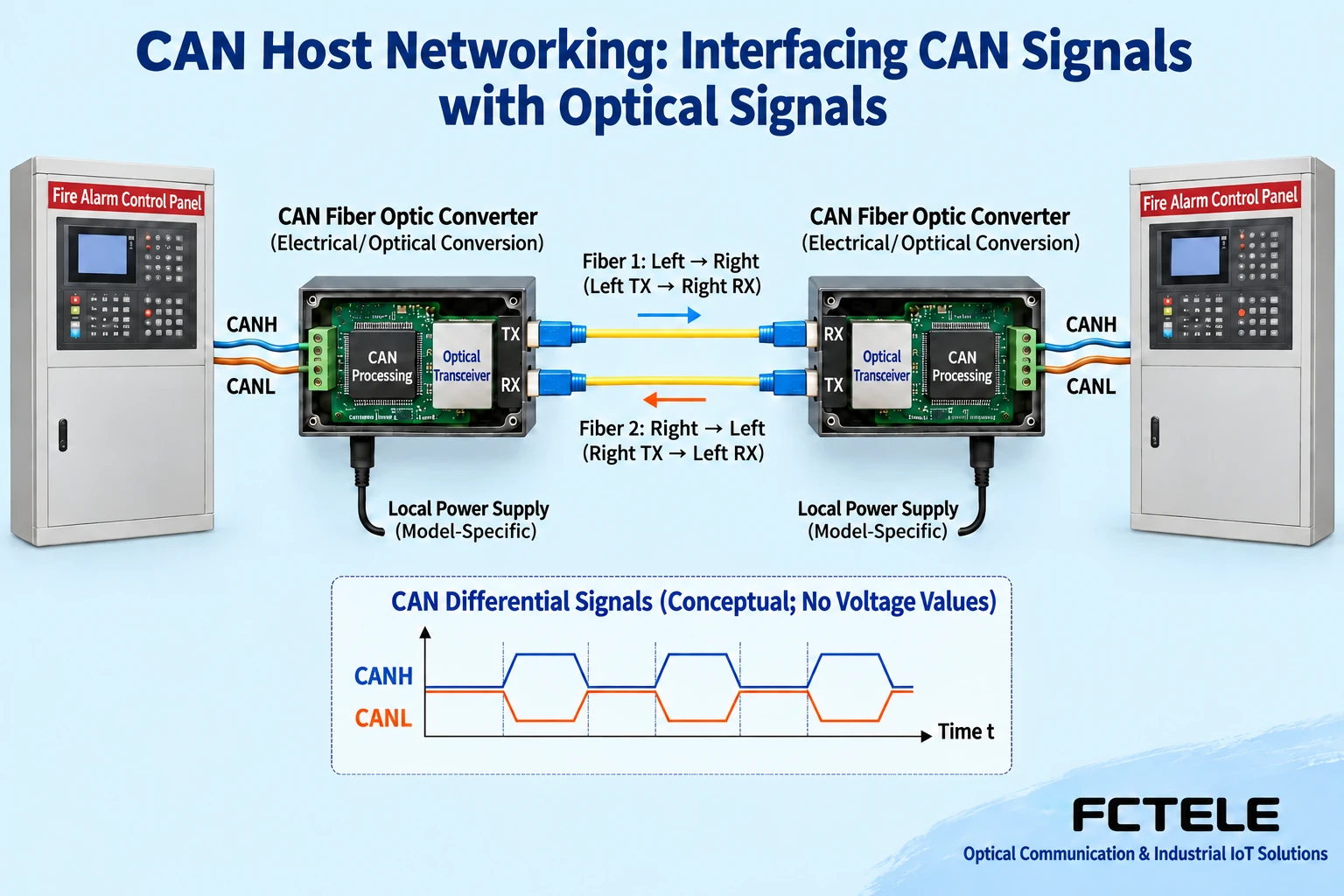
The CAN transceiver circuit identifies the bus state based on the relative potential of the two lines CANH and CANL, and the controller participates in communication according to the corresponding rules. The fiber optic transceiver converts the CAN communication it supports to an optical link, and at the remote end it hands over to another CAN network through a matching electrical interface. Whether a specific device extends at the bit level or receives frames and then forwards them affects timing and topology; you cannot assume internal processing is completely identical just because both are called “transparent.”
What is transmitted in the fiber is an optical signal, not the voltage of the CAN copper line moved directly to another building. Electrical-to-optical handover requires local transceivers, processing circuits, and optical modules to work together; the devices at both ends each have their own power supply. Paired dual-fiber links are usually checked by connecting the local transmit to the remote receive, while single-fiber devices need matching pairing methods and wavelength configurations. The same optical interface appearance does not prove that two dedicated CAN fiber optic transceivers can interoperate.
3. Why Distance Limits Cannot Be Reduced to a Single Number
CAN communication involves nodes observing bus status and the corresponding arbitration and acknowledgment timing. Signal propagation, circuit processing, and wiring all take time; the higher the rate, the shorter the time available for each bit is usually. How far a given line segment can transmit must be judged together with the device mechanism, communication parameters, and overall configuration. You cannot use “copper cable is only limited beyond 10 kilometers” as a general starting point, nor can you treat the optical module’s nominal distance as the permitted distance for the entire system.
Bit-level extension needs to consider the delay of the entire communication path; bridging or store-and-forward with a controller may reorganize communication on the bus segment while introducing queuing and processing behavior. Which end generates acknowledgment and how errors and congestion are handled must be checked in the device documentation. The fact that an optical link can be established does not mean the original panel’s response deadlines, node organization, and application handling are all satisfied. When choosing, record the farthest line, segmentation structure, load, and permitted behavior; do not decide based on promotional slogans.
4. Transparent Transmission Does Not Equal Business Compatibility
The CAN identifier is part of the message structure, and it does not mean the manufacturer must assign the same alarm meaning to the same identifier. Two panels that both have CAN interfaces may use different event codes, node management, and networking permissions. The original text lists multiple brands and claims broad compatibility, but does not give the corresponding models, networking boards, versions, and test results; this article does not use that list as compatibility evidence.
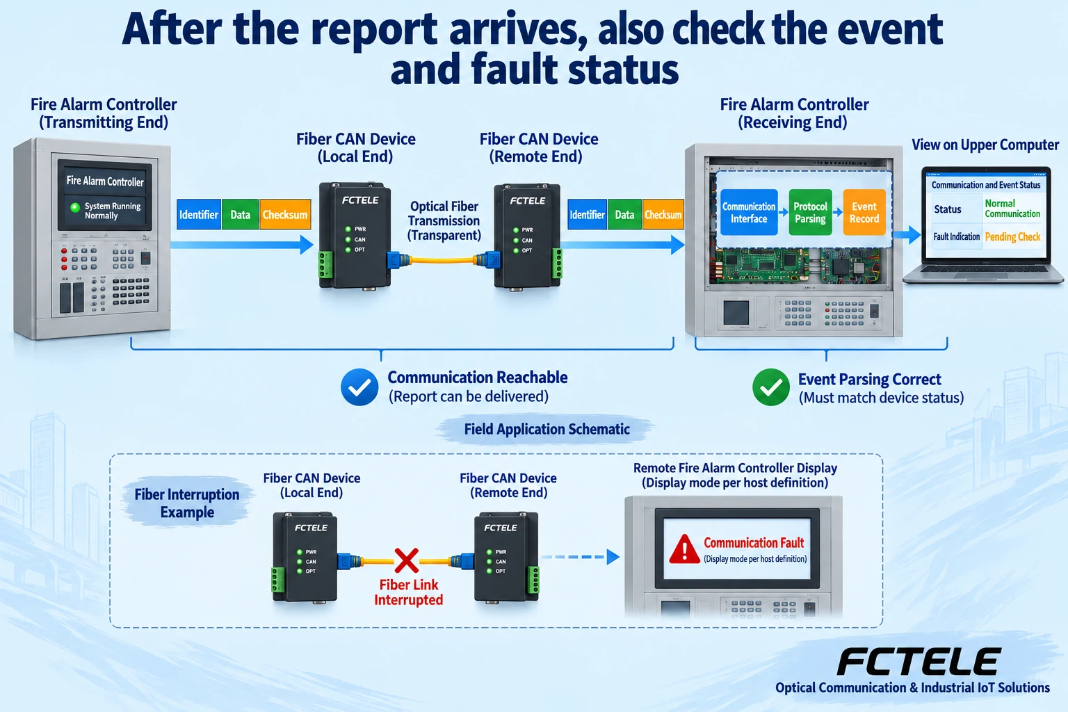
Even if the identifier and data arrive completely, the receiving panel still needs to correctly interpret the event according to its own protocol. Being able to see bytes or frames and being able to display the correct point, event category, and status are two different acceptance levels. A general-purpose converter does not automatically complete cross-brand alarm protocol conversion; when a dedicated gateway is involved, a clear support scope and test records should still be obtained. Hardware connectivity cannot replace system function verification.
5. What Fiber Optic Isolation Can Help With
Using fiber between two devices can reduce the electrical coupling path formed along long-distance signal copper cables, which helps cross-building communication wiring. However, the device’s local CAN port, power supply, enclosure, and other copper cables are still in their respective site environments. You cannot write that using fiber makes the device completely immune to lightning strikes, arbitrary electromagnetic interference, or power supply abnormalities. Protection and installation still need to be implemented according to the specific product and project requirements.
Contamination on the optical cable end face, excessive bending, connector loss, or mismatched optical modules can also cause communication problems. A power supply fault may appear similar to a broken fiber; troubleshooting should first record the power and status at both ends, then check the optical path, CAN end, and panel events. Do not look directly at the optical interface; use appropriate tools for optical power and line inspection; local electrical measurement and installation should be completed by personnel with the corresponding capabilities, and so-called absolute protection should not be verified through dangerous interference tests.
6. How to Check Feichang Technology’s Specific Products
The Feichang Technology CAN category includes different structures such as point-to-point, aggregation, and ring network; the capability of one model cannot be directly extended to the entire series. The FCM-C1/2 public details list the CAN interface and optical interface and can serve as candidate material for the corresponding CAN fiber extension; it explains why the local electrical interface can be combined with a remote optical link, but it cannot serve as proof that a certain fire alarm panel has been adapted. The actual ordered version, conversion mechanism, and connection methods permitted by the panel manufacturer must be confirmed.
Different paragraphs of those details differ in their descriptions of the interface maximum rate, power supply, and form factor; during procurement, you should request formal specifications and configuration answers for the corresponding model, and not assemble a device with all parameters from different paragraphs of a web page. Baud rate adaptation also does not mean that any two segments can use different rates, and it certainly does not mean support for all CAN FD or proprietary networking modes. This article does not carry over temperature, distance, delay, and brand promises from old articles that have not been verified for the corresponding model.
7. From Controlled Short-Link Verification to Formal Lines
First, in a test environment confirmed by the party responsible for the system, establish a short-link baseline according to the original manufacturer’s networking documentation. Record the panel, networking board, firmware, converter, interface parameters, and node addresses, and let a known, identifiable test event travel along the link to the receiving end. The corresponding personnel should use the test methods provided by the panel, and avoid creating alarms or triggering actual linkages without authorization at an operating site; test results must state the conditions and must not be passed off as formal project verification.
Check the time, point, event category, and recovery status at the sending and receiving ends, then gradually add the planned lines and nodes. When simulating a broken link, power loss at one end, and reconnection, observe how the communication fault appears, whether the old state is retained, and whether events are repeated or missing after recovery. Link loss should display a communication fault as defined by the panel; a broken fiber must not be directly equated with a fire, and the last normal screen must not be allowed to hide an actual loss of connection.
8. Alarms and Recovery Need System-Level Evidence
CAN error statistics, optical port status, and power indicators can help locate problems, but they may not cover all panel business. Maintenance personnel should separately record optical path reachability, CAN handover, and event interpretation results, and not replace the three proofs with a single green light. After connection recovery, it is also necessary to verify that the panel re-identifies nodes, that events are consistent, and that fault clearing behavior works; you cannot assume that once communication is restored, all previous events will automatically be filled in.
The formal plan should leave topology, terminals, cables, versions, configuration, test records, and rollback steps, and clarify who is responsible for panel functions, who is responsible for transmission lines, and who is responsible for maintenance. After capacity increases, topology changes, or firmware replacement, re-checking should be done according to system requirements. The value of a CAN fiber optic transceiver is to provide a suitable transmission path; whether this path can be used for a specific alarm system requires evidence of the corresponding interface, model, and complete business verification.
Verification materials: Feichang Technology CAN product category ;FCM-C1/2 public details; TI CAN arbitration and physical layer test materials . Public product descriptions are manufacturer statements; adaptation conclusions are subject to the corresponding version documentation and system verification. This article explains communication principles and does not replace the original manufacturer’s fire system design, commissioning, and acceptance documents.
Translated from the Chinese technical article. Source first published: 2021-04-12. Source last revised: 2026-10-13T11:01:30+08:00. Read the Chinese source
