


A wireless bridge is suitable for connecting two locations where cabling is inconvenient into one network path, for example sending network camera images from a factory gate back to a duty room. What it reduces is the data cable construction across that distance; it does not supply power to the camera or remote equipment through the air, and it does not automatically improve camera image quality. Whether it is worth using depends on line of sight, wireless capacity, on-site power, maintenance conditions, and actual service requirements.
1. First distinguish the work of the camera, the bridge, and the recorder
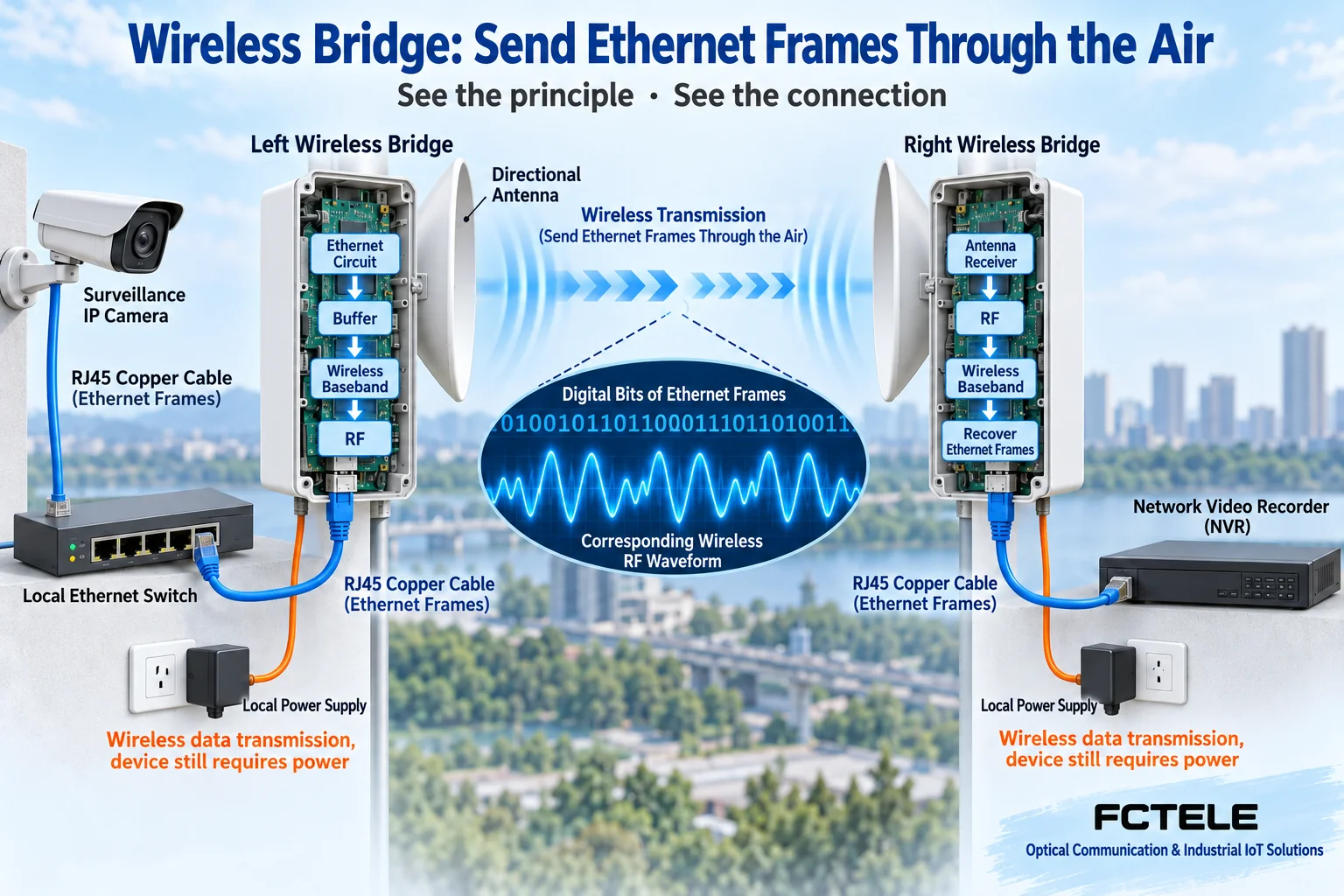
A network camera encodes images into video data and sends it out through an Ethernet port. An on-site switch aggregates this data, and the wireless bridge then sends the data through the air; the other end restores it to Ethernet data and hands it to the recorder or central network. An analog camera cannot become a network camera with just a bridge; it needs corresponding encoding equipment. The bridge is responsible for transmission, and the camera is responsible for imaging and encoding; the two responsibilities must not be mixed together.
Taking common bridge mode as an example, the sending end receives Ethernet frames, goes through buffering and wireless baseband processing, maps the information onto wireless signals, and sends them out through the radio frequency circuit and antenna; the receiving end completes the reverse process and then hands the data to the Ethernet interface. The specific wireless encapsulation and scheduling method depends on the device. “Transparent” here means that data meeting the supported conditions can cross the link; it does not prove that all VLANs, multicast, and control messages require no configuration.
2. Point-to-point: two ends facing each other, verify one link first
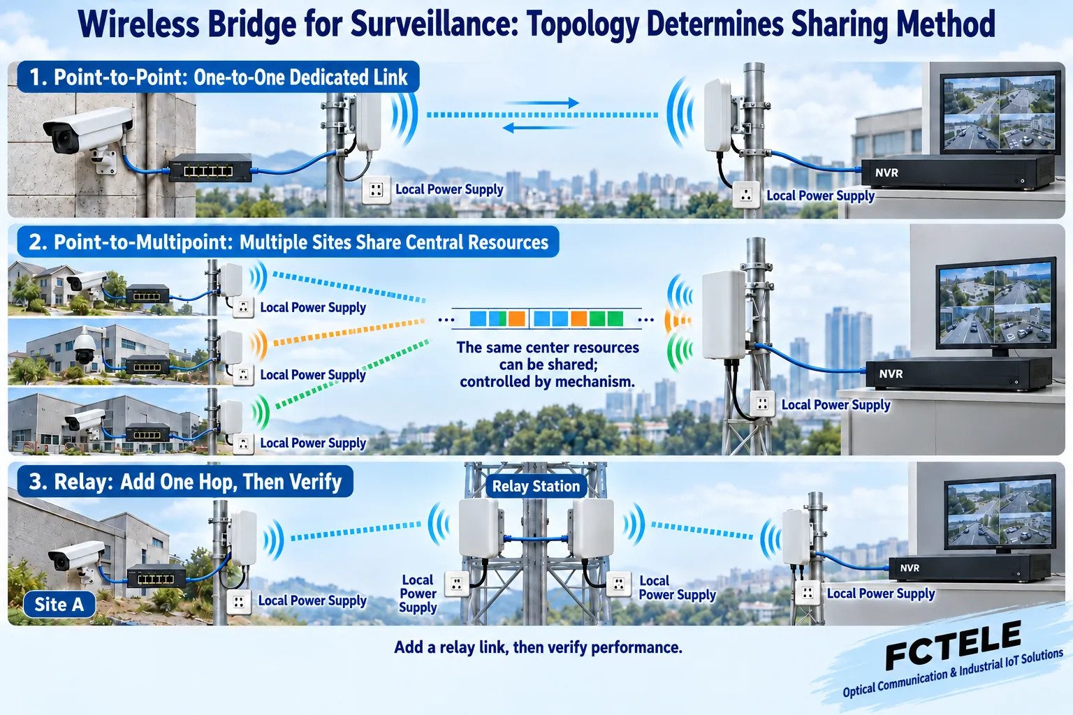
Point-to-point usually means on-site equipment on one side corresponds to central equipment on the other side, with wireless devices at both ends that support the corresponding mode. The on-site camera connects to the wireless bridge through a switch or network cable, and the central bridge connects to the central network through a network cable. Antenna installation position, direction, and polarization should be checked against product documentation, and the frequency, bandwidth, security settings, and roles at both ends must also be compatible. The fact that both devices can open their management web pages does not mean the over-the-air service channel has been established.
For example, if a gate has several cameras, you can first aggregate them on the same side with a switch, then send them back to the center through a pair of bridges. What needs to be checked is the concurrent traffic and peak traffic of all video, not simply converting the number of cameras into the number of bridge ports. Adding one high-bitrate camera may cause an originally stable wireless link to begin queuing or dropping packets; you cannot assume wireless capacity is sufficient just because the electrical port is labeled gigabit.
3. Point-to-multipoint and relay: results from one pair of devices cannot be copied directly
Point-to-multipoint means the center accesses multiple on-site directions. The center coverage angle, number of clients, uplink/downlink ratio, and scheduling capability must all be selected according to the model; multiple sites may share the center’s wireless resources. If one site has a weak signal and many retransmissions, it may also occupy more airtime. The fact that a supplier uses contention access or a dedicated scheduling mechanism does not mean all wireless bridges work in the same way, and even less does it mean each direction exclusively enjoys the advertised rate.
When there is obstruction between two endpoints, adding a relay station can be evaluated, but first check whether the relay location separately satisfies the propagation conditions of both segments. Using two sets of wireless links and handing off through Ethernet at the relay is a common solution; whether a single device supports relay and whether it shares radio frequency and channel depends on the specific documentation. Same-channel multi-hop often consumes more airtime; you cannot promise that capacity will remain unchanged in all cases, nor can you say fixedly without looking at the device that throughput is halved.
4. Seeing the roof is not enough; also check the propagation space
Line of sight means whether the central propagation path between the two ends is obstructed. The Fresnel zone is a space around this path that needs attention: treetops, wall corners, or roofs may still affect propagation even if they do not completely block the center line. Therefore, an on-site survey should look at height, obstacles along the route, and future changes; “the opposite side can be seen with the naked eye” cannot be the only acceptance condition. Seasonal changes in leaves, shaking of mounting brackets, and new buildings may all change link performance.
The frequency band, channel width, and transmit settings need to be selected based on locally permitted use conditions, device documentation, and on-site interference. A wider channel is not necessarily more stable, and increasing power cannot replace correctly aiming the antenna, clearing obstructions, and planning channels. Outdoor equipment, cables, waterproofing, grounding, and protection should be installed according to installation requirements; you should not treat high-humidity, hazardous, or strongly interfering areas as unconditionally suitable just because the device can transmit data wirelessly.
5. Calculate bitrate, shared capacity, and power separately
First count the video bitrate planned to be returned simultaneously, then consider encoding changes, protocol overhead, retransmissions, and other services. A low average bitrate does not mean there are no peaks during nighttime noise, complex images, or simultaneous switching of multiple channels. The wireless nominal rate is not the application throughput continuously received by the recorder; testing should include actual resolution, frame rate, encoding method, and number of concurrent channels, and record whether images are continuous, whether key events are complete, and how latency changes.
Cameras, switches, and bridges all need clear local power. PoE is a method of supplying power through a network cable; the power sourcing equipment and powered device must be compatible in standard, power budget, and wiring conditions. Some wireless devices use passive power specified by the manufacturer; because the interface is also RJ45, you cannot directly connect it to any PoE switch; nor can you interpret 802.3af as always providing 12V. When using an adapter or injector on site, the actual model should likewise be checked.
Feichang Technology’s managed 8-gigabit electrical port plus 2-gigabit optical port switch can serve as one type of candidate for on-site wired aggregation; the PoE listed on the official website is an optional configuration. It can help aggregate the camera network, but whether it can power a certain bridge still needs to be checked against the selected ordering configuration and the bridge’s power receiving requirements; its number of optical and electrical ports will not increase the over-the-air link bandwidth. The page title, introduction, and parameter table differ in the number of optical ports, and the model column is also not clear; the actual ports and ordering model should be confirmed first, and you cannot place an order based on just one title. When fiber laying conditions are available, you can also compare Ethernet fiber transmission solutions , and choose according to maintenance and service requirements.
6. Before going live, accept the entire service, not just do one Ping
First confirm that the local camera and switch are normal, then build a short-distance wireless baseline, and finally install at the formal positions. Record device roles, addresses, channels, security methods, antenna positions, signal, and error indicators. Bridge mode usually still requires configuring an address for device management; if it is mistakenly switched to routing mode, the original network boundary may change, and you cannot judge that the service configuration is correct only by the indicator lights at both ends being on.
When the planned multiple video channels are running simultaneously, check recording playback, image continuity, alarm or control response, and peak-period performance. Ping only provides partial reachability information; it does not prove that all video has arrived. If a wired backup or a second wireless link is set up, check Layer 2 loop protection first; connecting two bridge paths at the same time may cause broadcast packets to be repeatedly duplicated, which instead affects the entire on-site network.
Management passwords, security settings, management access scope, and upgrade maintenance should have clear records, and configurations should be saved before changes. When testing power failure, link disconnection, and recovery, confirm that after the devices reconnect, recording and related services recover as expected. An ordinary wireless link solution cannot claim, based on a single demonstration, to have the reliability required by a security system or emergency system; it should be separately verified according to the project’s functional and acceptance requirements.
Documentation note: wireless bridging roles and networking methods refer to Ubiquiti airOS User Guide and LiteBeam official documentation ; these documents are used to explain the supplier’s specific implementation and cannot be used to infer that Feichang Technology models support the same wireless functions. This article merges the surveillance application and networking issues of the original 1394 and 1105; the illustrations are general principle diagrams, and distance, throughput, power, and compatibility are subject to the actual model and on-site verification.
Translated from the Chinese technical article. Source first published: 2020-04-22. Source last revised: 2026-10-13T11:01:30+08:00. Read the Chinese source
