

ETHERNET FRAME BOUNDARIES, AT A GLANCE
Why does useful throughput differ from port speed?
Each Ethernet transmission includes start signaling and follows gap rules before the next one begins. Short frames repeat these costs more often. The gap is outside the MAC frame and does not mean link loss. Define the speed, observation point and counting convention before comparing throughput or interpreting a capture.
Find the beginning
Preamble and SFD help identify the start. They are not user payload.
Keep the gap outside
For the common 100 Mb/s example, the MAC rule uses 96 bit times, not a universal duration in nanoseconds.
Separate waiting time
A wider observed interval can include queuing or application timing, not just minimum IFG.
Check the port
Record negotiated speed and duplex before applying a timing rule.
Check the capture
Identify whether preamble, FCS and physical timing are visible at this observation point.
Check the traffic
Keep frame size and offered load comparable, and retain loss and application evidence.
Selection and verification checklist — expand
| Check | What to confirm | How to verify |
|---|---|---|
| Scope | Speed and duplex | Read negotiated port state. |
| Counting | Payload, MAC frame or line overhead | Read instrument definitions. |
| Observation | Capture point and timestamp origin | Check adapter and tool behavior. |
| Load | Frame sizes and offered traffic | Retain the test setup. |
| Outcome | Loss, errors and application timing | Compare counters with service records. |
Conceptual diagrams, not measurements, product internals or a universal conformance procedure.
A port reporting 100 Mb/s or 1 Gb/s does not mean user data fills the link without interruption. Ethernet uses start signals before a frame and timing rules between successive transmissions. These are deliberate parts of communication, not faults or arbitrary blank space. Understanding them explains why small packets still consume link time and why capture length is not the same as total line overhead.
Three different views of one transmission
A status message from a PLC is placed inside an Ethernet frame: a data package with addressing and checking information. Transmitting that package also requires a way to identify its beginning and a rule for starting the next one after it ends. Application content, frame structure and the complete transmission on the link therefore describe different counting boundaries.
This explanation mainly uses a common 100 Mb/s full-duplex Ethernet setting. Full duplex means both ends can transmit toward each other at the same time, with a transmission process in each direction. It should not be explained as the old shared-medium process of competing for the line and handling collisions. The gap discussed here does not make the two directions take turns.
Think of a transmission as a short announcement with an opening cue: the receiver recognizes that data is beginning, reads the content and then follows the rules for the next announcement. The analogy is only about boundaries. Real ports handle electrical or optical signals and coding; nobody literally pauses to take a breath.
Preamble and SFD identify the beginning
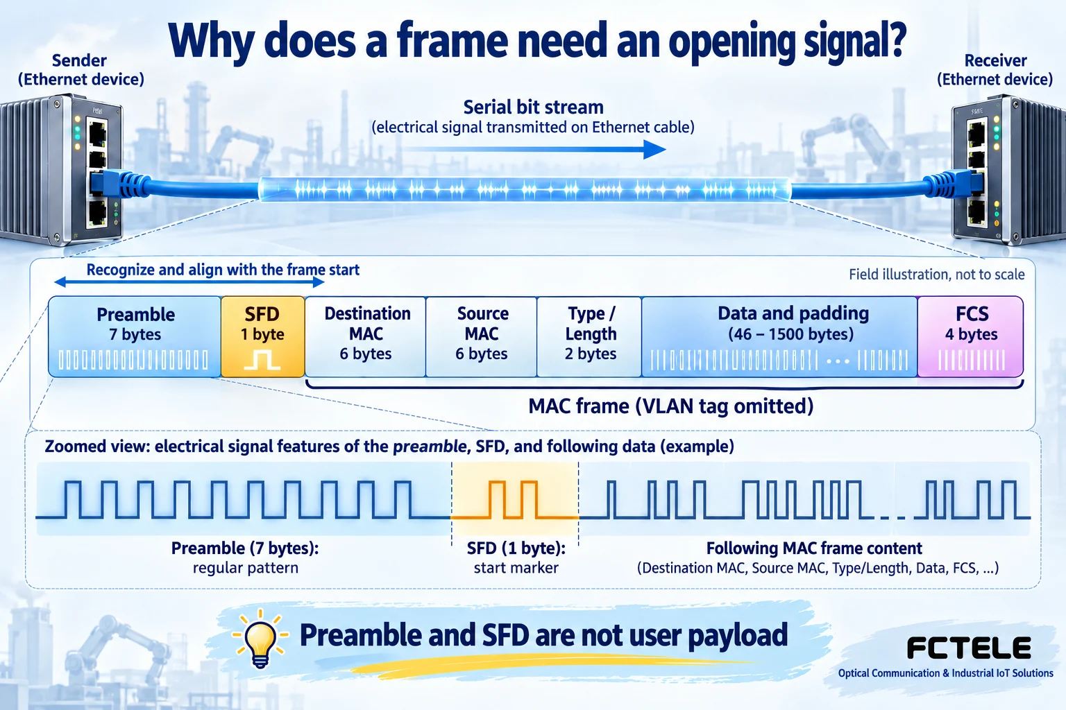
In a common MAC transmission representation, seven preamble bytes and a one-byte Start Frame Delimiter, or SFD, precede the frame. A byte is a group of eight binary bits. The preamble has a regular changing pattern, while the SFD identifies the boundary before the frame content. Together they help the receive process recognize and align with the beginning.
The destination MAC, source MAC and other fields follow, then data with any required padding, and finally the Frame Check Sequence, or FCS. Addresses help identify where the data is going and where it came from; FCS checks for errors. Start recognition and error checking do different jobs. Preamble is not another checksum, and SFD is not application data.
A modern PHY, the circuitry that handles physical transmission, reception and coding, may remain active while the link is connected. It is misleading to describe preamble as powering up the whole port again for every frame. Speeds and physical interfaces have additional coding details. The illustration shows useful transmission layers, not necessarily the literal byte sequence observable on every cable.
The gap is not padding inside the frame
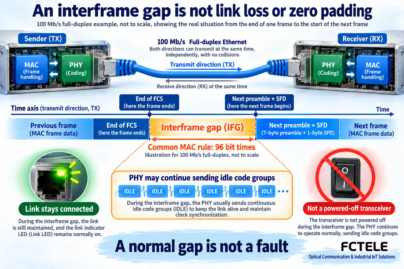
After one frame finishes, the next preamble must follow the applicable interframe-gap rules. IFG and IPG are commonly used for this idea. For the common 100 Mb/s MAC transmit setting discussed here, it can be understood as at least 96 bit times. A bit time is the time to transmit one binary bit at that rate. It does not mean a fixed 96 nanoseconds.
The gap is a position in transmission timing, not twelve zero bytes inserted into the data area. Padding is inside the frame and meets the applicable length requirement; the gap is between successive transmissions. Mixing them up can produce incorrect capture-length interpretations or the mistaken belief that extra application data was delivered.
The interval also does not mean that the transmitter switches off. Some physical layers continue sending idle code groups to maintain a normal link. The 100 Mb/s example illustrates the distinction: no current business frame does not necessarily mean no signal on the medium, and it does not mean the port has entered an energy-saving sleep state.
A capture does not show every part of line time
An ordinary computer capture normally receives frames through the network adapter and driver. Preamble, SFD and interframe gap usually are not presented as normal captured-frame fields; some capture paths also remove FCS. The displayed content has already passed through hardware processing. It is not a photograph of every part of the physical transmission.
Before comparing lengths, establish whether an instrument is reporting application payload, Layer 2 frames or a statistic that includes particular line overheads. Capture timestamps may also depend on the driver, buffering and recording location. Subtracting two timestamps does not automatically measure the precise gap at PHY pins.
For strict timing validation, use equipment that covers the required observation point and verify calibration, counting boundaries and method. Without that evidence, describe the result as an interval observed at the application-side capture point. Do not present a software screenshot as a physical-layer measurement.
Why short frames repeat the opening overhead more often
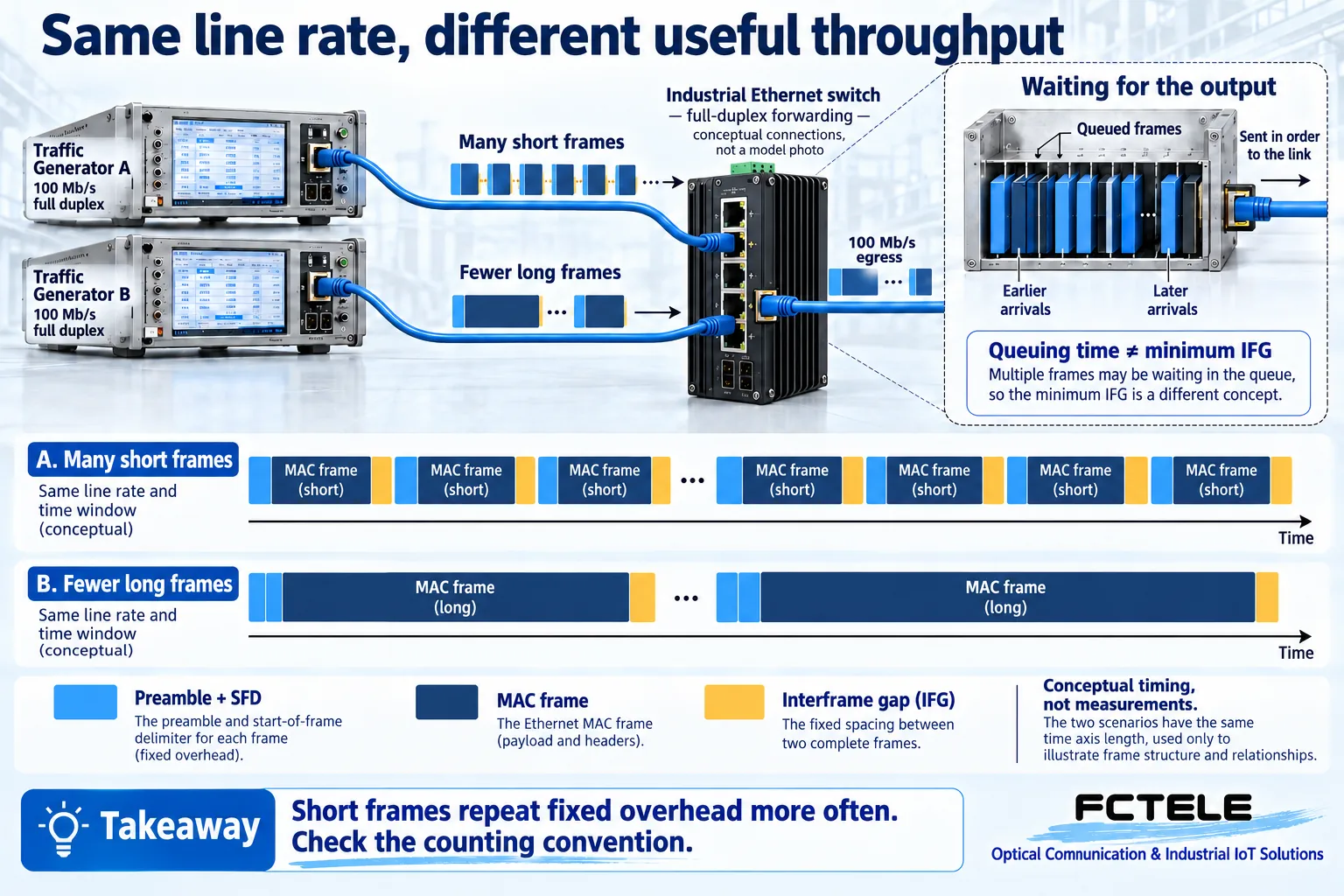
Each separate transmission has its own start and transition requirements, whatever its payload size. Compare a stream of many small packages with one carrying more content in each package. The former repeats opening and frame-boundary overhead more frequently. Port line rate and useful application data per second consequently are not automatically identical.
This is not a recommendation to combine every industrial control message into a large frame. Control data can have deadlines, and waiting to fill a batch may make fresh data late. A larger frame also occupies a longer individual transmission interval. Network decisions should consider the real frame-size distribution, sending frequency and permitted latency, not just one maximum-throughput figure.
A throughput test without frame size, direction, load, loss results and counting convention is difficult to compare fairly with another test. The short-versus-long-frame illustration only explains repeated overhead. It is not a performance test of a FCTEL switch and supplies no universal efficiency percentage.
Separate IFG, queuing and PAUSE frames
After receiving data, an industrial switch identifies an egress and schedules transmission. If several ingress ports feed one egress at the same time, data that has not yet been selected may wait in a buffer. This queuing time is different from the gap required by the egress transmission rules. A longer pause seen by an application can include both and other processing.
A PAUSE frame is another mechanism: adjacent devices can request that transmission be delayed according to their supported flow-control behavior. It is not a message transmitted during every IFG. Nor does a wider interval between two frames prove flow control occurred. Check relevant counters, actual frames, egress queues and load changes.
Understand a switched path one link at a time. Ingress and egress can run at different rates and transmit at different times. The output side follows its own transmission rules; it does not necessarily reproduce the incoming gap unchanged on another cable. Actual forwarding mode, delay and available counters depend on the device documentation.
Turn the principles into a useful site check
First verify negotiated port speed and duplex, then record the measurement convention used by the test instrument or adapter. When comparing short-frame traffic, hold frame size and offered load consistent while observing loss, error counters and application responses. Keep line-rate status, Layer 2 forwarding results and timely delivery to the control program as distinct evidence.
The FCTEL website offers industrial switches and optical communication equipment. For a particular project, verify the selected model’s ports, forwarding behavior, buffering and management visibility. Do not infer undocumented capabilities from a product name. Changing a driver option does not turn an ordinary network port into a calibrated gap analyzer.
The 100 Mb/s explanation must not be applied indiscriminately to all faster Ethernet interfaces. Higher speeds introduce different coding, alignment and idle-control mechanisms. In some implementations, a single interval at a given observation point and an average rule require separate interpretation. Use the relevant speed-specific specification and product documentation for conformance testing instead of changing low-level registers from this simplified picture.
Finish with three straightforward questions: who recognizes the start, what belongs inside the frame, and when can the next transmission begin? Separate those boundaries before discussing throughput or delay. A normal gap does not need to be eliminated, but unexplained waiting should not be dismissed simply because Ethernet includes gaps.
Sources and measurement boundaries
Cisco: Ethernet frame formats and troubleshooting; Microchip: transmit block and interframe gap; IEEE 802.3 historical discussion: higher-speed gap alignment. Checked October 19, 2026. A historical discussion does not replace the current full standard. AI-assisted original diagrams are conceptual, not product measurements. FCTELE product documentation governs specific model capabilities.
Translated from the Chinese technical article: Read the original Chinese article.
Common practical questions
Is the interframe gap zero padding added to the data?
No. Padding is inside a frame; the gap is between the end of one frame and the next preamble. It is not payload bytes. The PHY may continue transmitting idle code groups during that time.
Does a capture without preamble mean it was not transmitted?
No. Ordinary network adapters and drivers normally do not deliver all line-level start signals to capture software. Some capture paths also remove the FCS. Identify the observation point and length convention first.
Does a long pause between frames prove an IFG fault?
No. Queuing, application timing, flow control and the capture point can affect the observed interval. Check load, counters and measurement method before claiming a physical-layer violation.
Scope and further reading
General Ethernet framing principles and hypothetical examples, not measurements or a universal conformance test.
VLAN configuration principles (Chinese) · Ethernet FCS and bad frames (Chinese)
