


SERIAL BREAK, AT A GLANCE
Is BREAK a byte or a broken cable?
Neither. BREAK is a sustained spacing condition that extends beyond an ordinary character boundary at the receiving UART. A normal zero byte still includes its stop bit. An intact cable can carry BREAK, while a disconnected receiver may behave differently depending on its circuit. Remote serial networking must support the control operation as well as ordinary data transport.
Find the stop bit
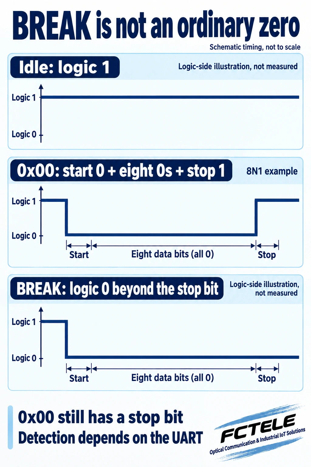
Ordinary 0x00 retains its stop bit. BREAK continues in the spacing state; detection conditions depend on the UART.
Find the interface
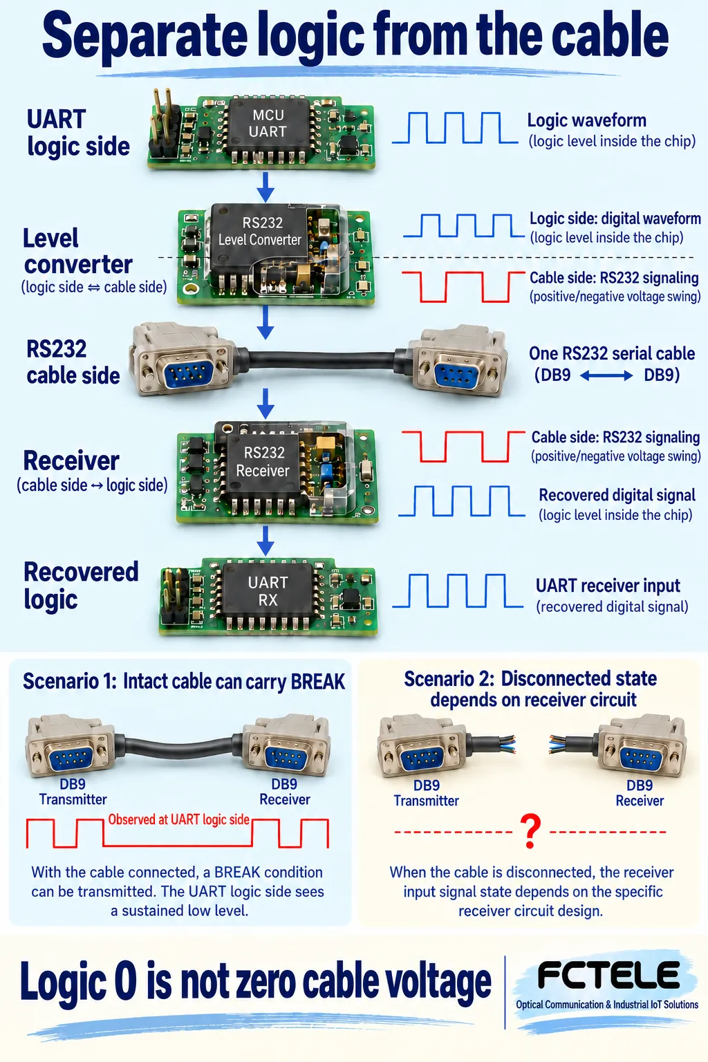
The drawing refers to the UART logic side. A cable disconnection does not guarantee a particular receiver state.
Find control support
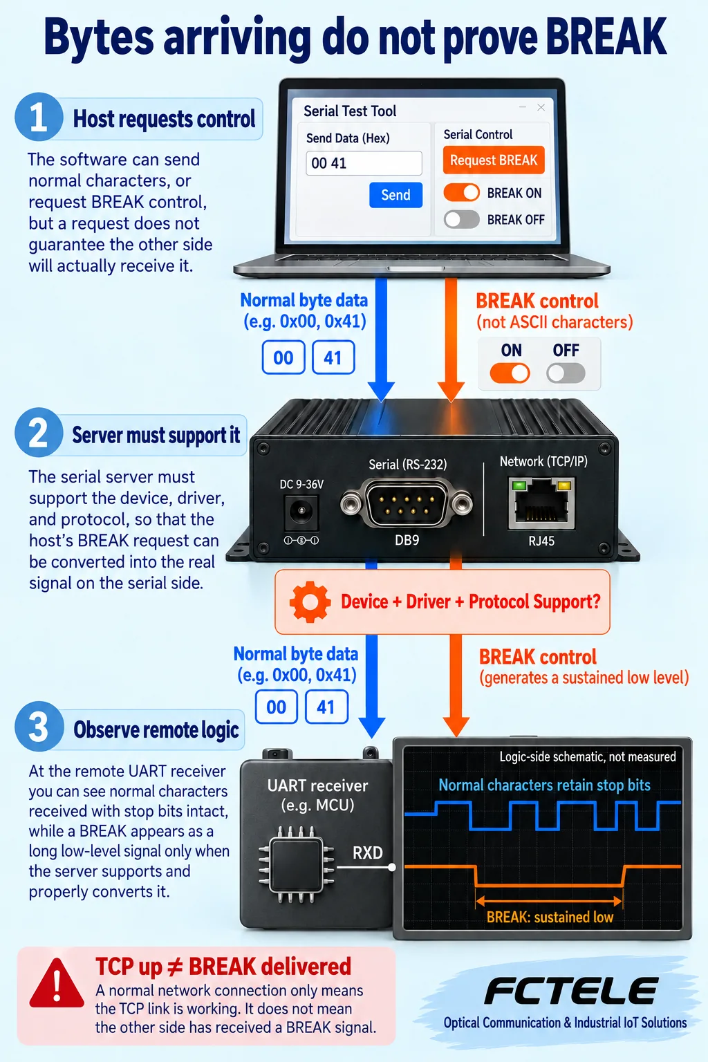
Verify generation, transport and release separately. Transparent byte transport alone is insufficient evidence.
Confirm the format
Record baud rate, data bits, parity, stop bits and the exact UART detection behavior.
Confirm the boundary
Observe a suitable logic-side test point; distinguish physical continuity from received signal state.
Confirm the outcome
Match host requests to remote observations and application logs in an approved test window.
Selection and verification checklist — expand
| Check | What to confirm | How to verify |
|---|---|---|
| Format | Same character timing at both ends | Retain actual settings and a known ordinary byte test. |
| Detection | UART and driver BREAK reporting | Read the selected documentation, not a universal threshold. |
| Interface | TTL, RS232 or RS485 | Check the product interface and instrument suitability. |
| Control | Local and remote generation and release | Verify device, driver and protocol capabilities separately. |
| Recovery | Return to idle and normal service | Release BREAK, send agreed characters and retain logs. |
Conceptual logic-side illustrations, not measurements, wiring instructions or claims of model-specific BREAK support.
Does the Send BREAK button in a serial utility send a text command or disconnect the cable? Neither. BREAK normally means that the transmitter maintains an active spacing state long enough for the receiver to see it extend beyond an ordinary character boundary. Start with how a character begins and ends, then separate the logic signal, the cable interface and remote control.
Start with how an ordinary character ends
A UART is the circuit that sends and receives serial data inside a device. Think of it as a small assistant that reads and writes one bit at an agreed pace. This article uses the common 8N1 format: one start bit, eight data bits, no parity and one stop bit. A bit occupies a short time slot. The receiver uses the agreed baud rate to decide whether the signal represents zero or one at the appropriate moment.
At a conventional non-inverted UART logic interface, idle is one. The transmitter first changes it to zero to announce a new character, sends the eight data bits and returns to one for the stop bit. The stop bit is not another written character; it is a level and time boundary that the receiver expects. Different formats or timing at the two ends can move the receiver sampling away from that boundary.
Suppose the receiver is expecting a complete character while the transmitter stays at zero from the start onward. The receiver may sample both the data and the expected stop position as zero. It cannot know the sender intent: hardware flags and software must interpret the observations. Whether the application treats this as a special request depends on an agreement, rather than being an automatic consequence of a long low state.
Why sending 0x00 is still different from BREAK
0x00 is a byte whose eight data bits are all zero. In 8N1 its start bit is also zero, so an oscilloscope shows an extended low portion. However, the character must still return to one for its stop bit. Repeated ordinary 0x00 characters retain their required stop bits. Seeing many 00 values in a window does not establish that BREAK is being transmitted.
Persistence is the key to BREAK. The transmitter maintains the spacing state through the position where the receiver expects a stop bit and satisfies the particular device detection conditions. It is rather like an expected word separator never arriving. That analogy concerns the boundary only: a long pause at idle one and a sustained spacing state are different conditions.
A pause between data transfers is another common source of confusion. Between two ordinary characters the transmitter may remain idle before beginning the next one. No character is carried during that interval, but the idle state is still valid. To identify BREAK, observe the signal state and its duration, rather than merely noticing that no new text has appeared.
What a framing error actually tells you
A receiver may report a framing error if it samples zero where a stop bit should be. The referenced Microchip USART documentation describes its FE flag in terms of stop-bit sampling. Some receivers combine zero data, a framing error and duration to recognize BREAK. Other circuits provide a dedicated BREAK indication. The actual reporting behavior must be checked in the chip and driver documentation.
A framing error alone does not prove BREAK. A baud-rate mismatch, a format mismatch, noise or interface faults can also corrupt the stop-bit sample. Likewise, there is no one fixed millisecond duration or bit-count threshold that applies to every UART. Record the format, rate, duration and actual error indications, and distinguish observing an anomaly from establishing an intentional BREAK request.
Some serial utilities hide error information and display only bytes; others separately report framing errors or BREAK events. Different windows on two computers do not necessarily mean different signals on the wire. Establish whether the utility retains error status before deciding whether an oscilloscope or logic analyzer is needed. A display difference alone is not evidence of incompatibility.
Logic zero is not the same thing as cable voltage
An RS232 interface normally has a level converter between the UART logic pins and the cable. It converts chip-level signals into the electrical signaling required on the cable and converts received signals back to logic. Zero and one in the waveform illustration describe the logic side. Do not directly equate the sign of a measured cable voltage with high or low at a chip pin. An RS485 differential interface must also be distinguished from single-ended RS232.
After a cable is disconnected, receiver behavior depends on factors including fail-safe design, biasing, power and interference. It is not guaranteed to become BREAK. Some receivers still produce stable idle when disconnected; other conditions can produce fluctuations. Conversely, a perfectly intact cable can carry BREAK normally. Cable continuity, interface power and received character state are three separate checks.
Before measuring, confirm that the instrument input, range and reference connection suit the actual interface. Do not connect a probe intended only for chip-level logic to an unverified industrial cable interface. These diagrams explain signal conditions rather than giving cross-interface wiring instructions. Grounding, isolation and power arrangements still require the selected equipment documentation.
Why serial networking may carry bytes but lose control
A serial device server carries serial data over a network and restores it at another interface. However, a byte-only channel may not transport line-control conditions such as BREAK. Sending the word BREAK produces ordinary text characters; sending 0x00 produces an ordinary byte. Neither substitutes for a driver or device operation that actually controls BREAK.
RFC2217 is one example of remote serial control: in addition to data, it defines control commands that can request BREAK on or off. It is an Experimental protocol. Its existence does not mean every serial device server supports it, and transparent TCP transport alone does not establish that capability. An active network connection proves something about that layer, not that the remote serial interface has entered the requested signal state.
Retain observations from both ends: when the host requested the operation, the server operating mode, and when the remote interface entered and left the sustained state. A successful command response may only show that one layer accepted the request. Match requests to physical observations to obtain evidence for the complete control path.
Verify product interfaces before assuming capabilities
The FCTEL website identifies FCT-1000-F1T1 as a single-channel TTL serial device server module. The relevant FCT-1200 series page distinguishes RS485 and RS232 interfaces. Those descriptions help establish the electrical interface; they do not establish identical BREAK transport capabilities. A TTL module must not be connected directly to an RS232 cable merely because both are called serial interfaces.
If a project requires BREAK, check the selected model documentation or ask technical support whether it can generate BREAK locally, control it remotely, set its duration, expose driver support and report it at the receiver. Also establish how the condition ends if a network fault occurs. Interface matching and control support are separate checks. This article adds no undocumented model features and does not present a generic drawing as a product internal architecture.
Specify ordinary data requirements and special control requirements separately. State the character format, whether ordinary traffic must be bidirectional and whether a special line state is needed. This helps both parties discuss concrete capabilities without treating network connectivity or byte reception as proof that every serial behavior has been preserved.
Build a test that reveals the cause
Use a maintenance window or an isolated test bench. First verify normal characters with a controlled transmitter and known receiver, retaining the actual format settings. Then transmit ordinary 0x00 and observe the stop bit. Test BREAK only after confirming that the equipment allows it, recording the command time, logic-side waveform and receiver log. Some terminals assign maintenance or special operations to BREAK, so do not casually press the button on operating control equipment.
Next add the serial device server and compare local and remote requests at the same observation point. If the network reports success but no sustained state appears remotely, investigate the driver, control protocol and device capabilities in turn. If BREAK is present remotely but the program does not react, examine receiver flags, driver handling and the application agreement. Change one layer at a time rather than attributing every symptom to a broken cable.
After testing, confirm that BREAK has been released and the serial interface has returned to its expected idle state. Send an agreed set of normal characters and check that service recovers. Retain successful and unsuccessful conditions, and repeat the relevant checks after changing a driver, firmware or operating mode. The objective is evidence from request to application response, rather than simply finding a button with the right name.
Sources and product evidence
TI: RS232 Design Guide, March 2026; Microchip: Receiver Error Flags; RFC2217, an Experimental remote serial-control protocol. Device-specific register and error-handling behavior must not be generalized.
Published product evidence: FCT-1000-F1T1 TTL module and FCT-1200 series RS485/RS232 interfaces. These Chinese-language product pages establish interface descriptions, not unverified BREAK capabilities.
Translated from the Chinese technical article: Read the original Chinese article.
Common practical questions
Does BREAK disconnect the serial cable?
No. An intact link can carry BREAK. The receiver state after disconnection depends on the circuit, power and biasing; disconnection alone does not establish BREAK.
Can sending 0x00 replace BREAK?
No. An ordinary 0x00 character still has its stop bit. BREAK maintains the spacing state beyond a normal character boundary and must meet the particular UART detection conditions.
Does transparent serial networking guarantee BREAK support?
No. Verify the device, driver and control protocol separately for generation, transport and release of BREAK, then observe the remote serial interface.
Scope and further reading
Generic asynchronous UART principles and conceptual illustrations, not measurements, cross-interface wiring instructions or verified model BREAK support.
Serial communication principles · Related serial engineering guide
