


MODBUS DATA INTERPRETATION
Why can communication succeed but a reading be wrong?
A successful exchange delivers register contents, without proving how the application should interpret them. A 32-bit value needs the correct whole-word arrangement, data type, scaling and unit. It also needs coherent update timing. Start with the device register map and retain the raw response. These are generic concepts, not a particular instrument configuration or a guarantee of atomic snapshots.
Bytes
A standard 16-bit register is carried as two ordered bytes.
Words
Rebuild whole words using the device map and the correct data type.
Moments
Check whether both words belong to one coherent update.
Confirm address notation, register count, type, scale and unit.
Save one authorized read request and its matching response.
Verify update behavior and any gateway cache timestamp.
Selection and verification checklist — expand
| Check | What to confirm | How to verify |
|---|---|---|
| Encoding | Byte and whole-word order | Compare raw bytes with the official map |
| Meaning | Data type, scale and unit | Check several known values |
| Freshness | Coherent updates and cache age | Read implementation and timestamp evidence |
An instrument displays 25, while the computer shows an implausible decimal value and the communication log reports success. The cable or fiber is not necessarily faulty: the data may have arrived intact and then been interpreted incorrectly. Understanding Modbus word order does not require a page of equations. Follow what a register contains, how a message carries it, and how software rebuilds the value to distinguish successful transport from a correct reading.

Start with numbered data compartments
Modbus defines rules for exchanging industrial device data. When reading holding registers or input registers, imagine the device data area as a row of numbered compartments. Each such register holds 16 bits, or two bytes; each byte contains eight bits. These are logical data units, not a claim that the instrument contains a physical row of separate chips.
The number tells software where to look, without fully explaining what is stored there. The same two bytes might represent an unsigned integer or a collection of status flags. A device register map explains whether the data means temperature, pressure, energy or something else. Treat the map as a packing list: address, data type, unit, scaling and validity conditions belong together. Copying the address alone is insufficient.
Check the address notation too. A manual may use a holding-register reference such as 40001, while the message uses a starting offset; some software performs the conversion for the user. Compare an example request in the same documentation to establish whether the interface expects a reference number or an offset. This avoids shifting the entire reading by one compartment. Repeatedly swapping words to compensate for an address error only makes diagnosis harder.
Which byte leaves a register first?
The example register value 0x1234 can be separated into bytes 12 and 34. Hexadecimal notation is simply a compact way to record raw data, rather than an advanced calculation required in the field. Standard Modbus register encoding places the high byte, 12, before the low byte, 34. Receiving software uses that order to recover the same 16-bit content.
This describes byte order in the message, which must not be confused with the order of individual serial bits within a byte. Computer memory layout is another separate matter: a processor’s native storage arrangement does not authorize an application to change the protocol’s message encoding. A capture shows message bytes; a debugger may already show a converted memory value. Identify the observation point before comparing them.
Two registers introduce word order
A 32-bit value cannot fit in a single 16-bit register and normally occupies two adjacent registers. Beyond byte order within each register, another question appears: does the earlier register hold the high 16 bits or the low 16 bits of the complete value? That is the word order discussed here. Devices and configurations can differ, so support for Modbus does not establish a common arrangement by itself.
For example, 25.0 in IEEE 754 single-precision floating-point format has the four bytes 41 C8 00 00. One illustrative register map places 41C8 in register N and 0000 in N+1; another reverses the two words. Both produce 25.0 when read and reconstructed according to their own maps. Applying the first interpretation to the second can produce a completely wrong value despite a successful exchange. These are teaching examples, not actual instrument addresses or settings.

Swapping words differs from swapping bytes within words
Imagine two books, each with an upper and lower page representing four data bytes. Exchanging the positions of the books resembles swapping two 16-bit words; exchanging the pages inside each book resembles swapping bytes within words. The operations affect different boundaries. Software labels such as big-endian, little-endian or swap may refer to different levels, so a menu name alone is insufficient to identify the transformation.
Record the four raw bytes in received order and write the software’s reconstruction order beside them. Change one clearly identified interpretation setting at a time and compare it with the official register map. Avoid applying the same swap blindly to every point or treating one plausible number as proof that the entire map is correct. Values near zero can conceal an ordering mistake, so check several known, distinct values.
The CRC at the end of a Modbus RTU frame is an error-detection code that helps check whether transmitted content has changed. If a device intentionally returns low-word-first data, its CRC can be valid. Software subsequently interpreting it as high-word-first will not cause the CRC to report that interpretation error. Reading a different but valid address can also pass the check. Keep separate evidence of what arrived and how it was interpreted.
The same bytes can require different interpretations
Correct ordering is only one requirement. A 32-bit integer and a 32-bit floating-point value use different interpretations. Floating-point formats can represent fractions, but that does not mean every four-byte item should be decoded as a float. Signed integers allow negative values, while unsigned integers use a different range interpretation. Obtain those choices from device documentation rather than guessing from how reasonable the screen looks.
Scaling and units are also part of the interpretation chain. If a register map explicitly says that raw integer 253 means 25.3 degrees Celsius, software should apply that convention rather than displaying 253 degrees Celsius. This is a separate example from the floating-point value 25.0 above. Check invalid-value encodings, offline indicators and reserved bits as well. Plotting a special unavailable code as a normal measurement can create a convincing but false process disturbance.
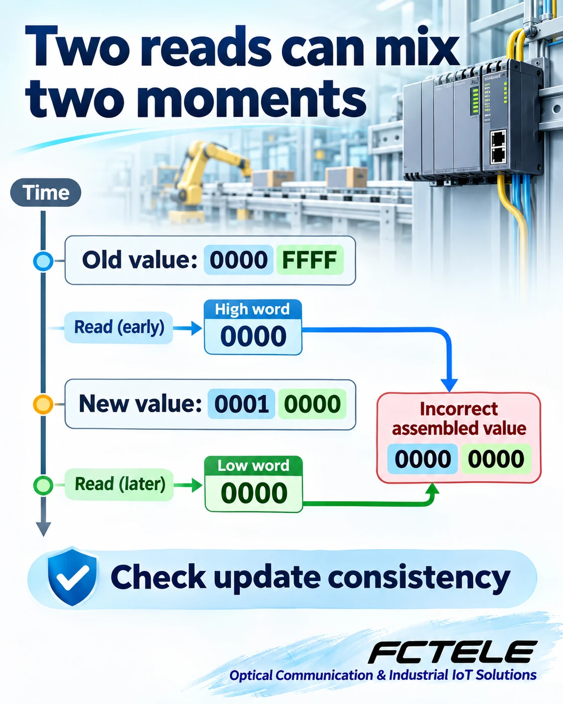
Correct order still needs a consistent sampling moment
When two registers are read in separate requests, the device can update between the reads. Consider an illustrative 32-bit unsigned counter changing from 0000 FFFF to 0001 0000. Reading the old high word 0000 and then the new low word 0000 produces 0000 0000. That result is neither the complete old value nor the complete new value. The problem is sampling consistency.
Reading two consecutive registers in one request usually reduces the window introduced by separate requests, but it does not prove that every device supplies an atomic snapshot. Check implementation documentation for latching, refresh behavior, sequence numbers or timestamps that identify a coherent update. If a gateway caches data, also record the cache update time. A newly returned message does not necessarily contain a newly measured value, and faster polling cannot replace a consistency mechanism.
Assign responsibilities along the communication path
FCTELE’s website lists the FCP-D8G industrial DIN-rail Modbus optical modem for point-to-point transport of Modbus serial communications over fiber. This illustrates a useful division: the optical link transports communication data, while the instrument register map defines its meaning. Using a Modbus optical modem does not establish automatic recognition of every instrument’s floating-point word order, unit conversion or synchronized measurement snapshots. Verify actual capabilities against the applicable product version documentation.
Begin verification with one device and one authorized read-only point. Save the request and response from the same transaction, confirm the target, function code, starting-address convention and register count, then check raw registers, word order, data type, scaling, units and update time. A successful integrity check is one step, rather than proof that the business interpretation is correct. Explain and document this complete reading chain before extending the work to other points. The record then supports systematic checks when an instrument or software package changes.
If a point reads correctly with a local tool but incorrectly across an optical link, compare raw responses from the same device under the same configuration, then inspect channel selection, serial settings and logs. Identical raw bytes with different displayed values point toward decoder settings; different bytes or mismatched transactions call for further investigation along the communication path. This order reduces unnecessary hardware replacement without dismissing genuine transport faults as word-order problems.
References and scope
Modbus Organization: registers and data formats; Application Protocol V1.1b3, section 4.2: byte encoding; Schneider Electric: register mapping and word-order examples; Schneider Electric: reading swapped floating-point values; FCTELE FCP-D8G Modbus optical modem information (Chinese). Third-party settings do not establish FCTELE product capabilities. Illustrations and examples are independently created explanations, not measured results or wiring instructions.
Translated from the Chinese technical article: Read the original Chinese article.
Common questions
Why can a successful Modbus exchange still show a wrong value?
Transport and interpretation are separate. Check the target, address convention, register count, word order, data type, scaling, unit and update time. A valid CRC does not prove a correct business interpretation.
Is swapping two registers the same as swapping bytes?
No. One changes the positions of complete 16-bit words; the other may change byte positions within a word. Check the device map and actual reconstruction rather than a menu label alone.
Does one request for two registers guarantee one sampling moment?
No. A block read can reduce the window introduced by separate requests, but atomic snapshots, latching and refresh behavior depend on the implementation. Cached gateway data also needs an update-time check.
Further reading
Multiple PLCs and a Modbus hub · UART byte framing and sampling
