


Multiple PLCs can share the same group of Modbus RTU instruments by using an FCC-D2M or FCC-D4M buffered hub to coordinate master requests, followed by an RS-485 hub with one upstream port and 8, 16 or 24 downstream branches. The first stage determines which request proceeds; the second distributes the field wiring. PLCs may initiate access concurrently, but requests and replies still pass through the shared downstream channel one transaction at a time. Every slave address must be unique across the whole shared network.
How can several PLCs share one group of serial instruments?
Separate the two jobs: a buffered coordinator manages competing master requests, and a downstream hub distributes the field wiring. Each PLC uses its own coordinator port. All instruments share one address plan and serial transaction capacity. This arrangement supports shared read access; it does not guarantee simultaneous samples, multiplied throughput or conflict-free writes.
01 · Coordinate
Connect each PLC to its own master-side port. Verify replies return to the requesting PLC.
02 · Distribute
Use an RS-485 upstream branch hub and one unique address plan for all field instruments.
03 · Budget time
Measure the polling cycle, offline-device waits and maximum queue delay before setting PLC timeouts.
Check ports
Match 2 or 4 PLCs to the corresponding coordinator. Confirm the downstream hub has an RS-485 upstream interface.
Check addresses
Record every instrument address once across the full shared network; test for duplicate replies.
Check failure behavior
Test an offline slave, a late reply and a branch fault while other PLCs continue reading.
Selection and verification checklist — expand
| Check | What to confirm | How to verify |
|---|---|---|
| Coordination | Multi-master mode and reply ownership | Issue overlapping read requests from separate PLC ports. |
| Branching | 8 / 16 / 24 branches; RS-485 upstream | Check the delivered hub variant and terminal definitions. |
| Timing | Queuing, retries and offline waits | Record worst-case response time under representative load. |
| Data meaning | Register map and byte order | Compare decoded values on each PLC with the same instrument. |
| Control | Read-only initial deployment | Design ownership and interlocks separately before enabling writes. |
Conceptual mechanisms, not internal circuitry, timing measurements or terminal wiring instructions.
1. Why does directly paralleling several PLCs cause problems?
A retrofit often starts with a simple request: the production PLC reads the instruments, the energy-management PLC needs the same measurements, and a monitoring PLC is added later. Each instrument has only one RS-485 interface. The aim is to share the existing equipment without installing several separate measurement circuits. A PLC is a programmable logic controller; Modbus RTU is a serial request-and-reply protocol, while RS-485 is the electrical interface carrying its signals.
In a conventional Modbus serial network, one master sends a request and the addressed slave replies. If the A and B wires of several masters are simply joined, two PLCs may transmit at once, or one may begin another request before the earlier reply arrives. Electrical activity on a cable does not establish that complete data has reached the correct requester. An ordinary single-master, multiple-slave hub expands the wiring; it does not automatically provide multi-master coordination.
2. Two stages with different jobs: coordinate first, branch second
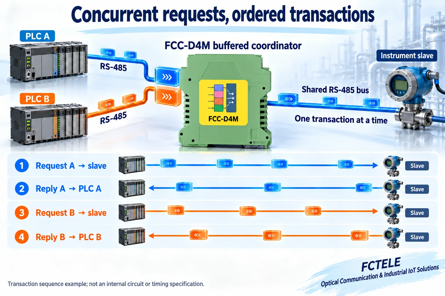
Use an FCC-D2M, with two master-side ports and one field-side port, or an FCC-D4M, with four master-side ports and one field-side port, in multi-master mode. Connect each of the two or four PLCs to its own master-side interface. Connect the coordinator’s field-side interface to the RS-485 upstream port of the downstream hub. The buffered device coordinates requests from different PLCs, forwards them in sequence, and returns each reply to the PLC that initiated that request. FCTELE has confirmed this cascade arrangement and reply routing for the solution described here.
The term “one slave” in the coordinator’s port description refers to one field-facing interface. It does not mean that the complete system can connect only one instrument. A single-master, multiple-slave hub behind this interface divides the field wiring into branches. Options are the FC-D8JM with 8 branches, FC-041719-16 with 16 branches, or FC-041719-24 with 24 branches. This solution uses the RS-485 upstream version in every case. Do not connect additional PLC masters directly to the downstream branch hub.
Published FCC-D2M/D4M information specifies a communication buffer of up to 10K bytes and configurable interface parameters. This supports the explanation of communication coordination. It does not establish that the device independently polls every register and then distributes the same stored historical values to all PLCs at high speed. Any such register-data caching function requires a separate, explicit specification.
3. Example: four PLCs reading 32 Modbus instruments
Consider an illustrative building or workshop project containing 32 instruments, such as energy meters and temperature controllers. Connect the four PLCs to the four master-side ports of an FCC-D4M. Connect its field-side port to the upstream port of an FC-D8JM. Run the FC-D8JM’s eight branches to eight areas, with four slaves daisy-chained on each branch: 32 instruments in total. Each field branch still follows RS-485 bus wiring practice. Do not add arbitrary long star-shaped stubs at its far end.
Allocate addresses 1–32 across the entire system: branch 1 uses 1–4, branch 2 uses 5–8, and so on. Do not restart at address 1 on every branch. An ordinary branch hub does not create separately routed address spaces. The same request can reach several branches, so duplicate addresses can cause several instruments to reply at once. Program all PLCs against the same address and register map to access the same set of field devices.
For two PLCs, substitute an FCC-D2M at the first stage. Where the wiring needs more branches, illustrative alternatives for 48 slaves include 16 branches with three instruments each, or 24 branches with two each. These examples explain configuration choices; they are not field-capacity guarantees. Port count, electrical node loading, Modbus addressing and polling-cycle time impose different limits and must be checked together.
Six configurations: choose by the number of readers and field areas
All six cases are hypothetical, read-only acquisition arrangements using one buffered coordinator and one branch hub. Every PLC must support RS-485 Modbus RTU master operation. Slave addresses must be unique throughout the shared network. The illustrations show topology, not terminal pinouts, completed customer installations or measured system capacity.
Case 1: 2 PLCs + 8 branches, 24 slaves
FCC-D2M + FC-D8JM: 8 branches × 3 instruments = 24 slaves, addresses 1–24.
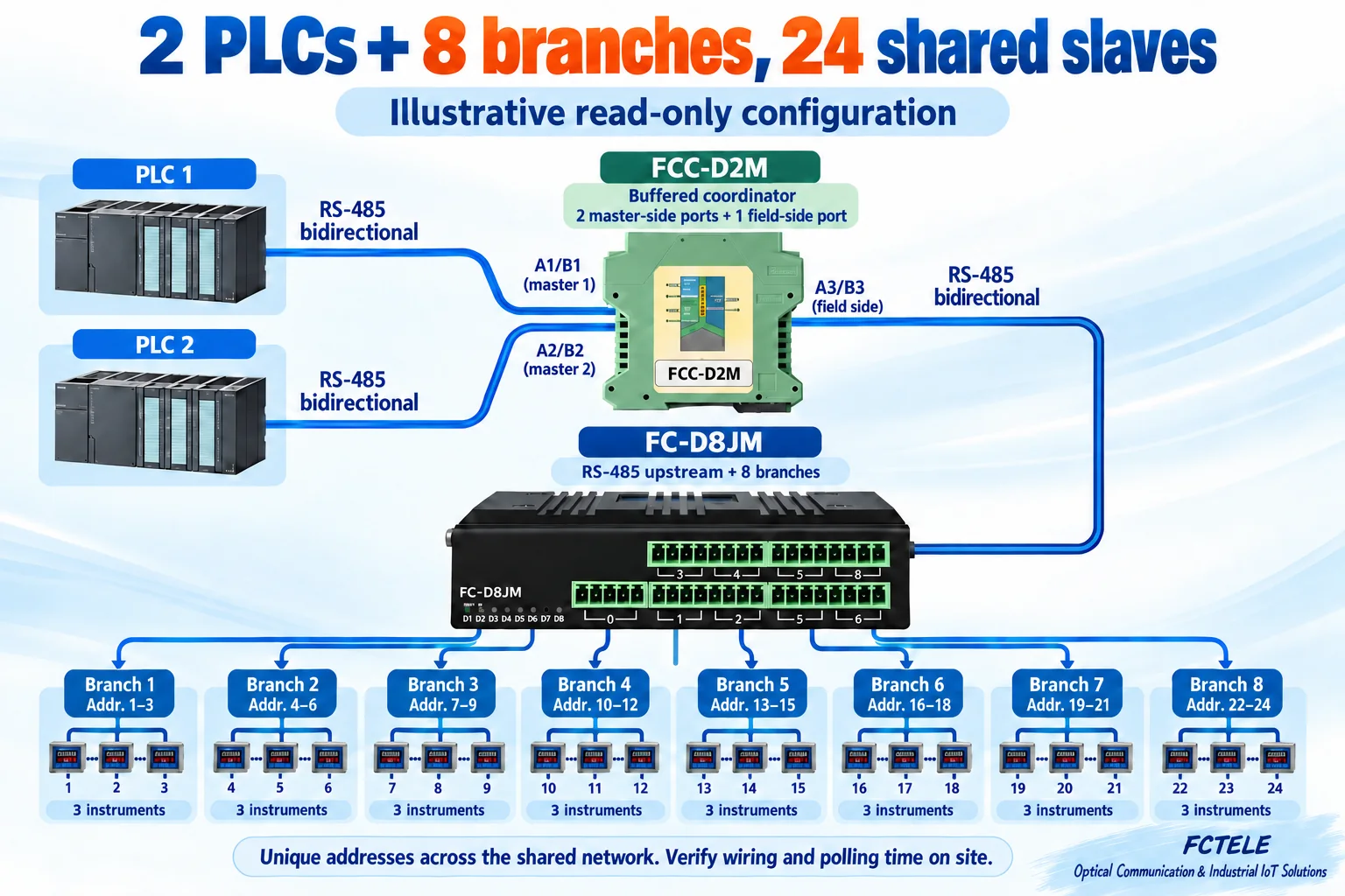
Two reading systems share instruments across a small number of areas. Eight branches with three slaves each use addresses 1–24; they can be organized by floor or cabinet while retaining existing serial instruments.
Addresses 1–3Branch 2
Addresses 4–6Branch 3
Addresses 7–9Branch 4
Addresses 10–12Branch 5
Addresses 13–15Branch 6
Addresses 16–18Branch 7
Addresses 19–21Branch 8
Addresses 22–24
Case 2: 4 PLCs + 8 branches, 32 slaves
FCC-D4M + FC-D8JM: 8 branches × 4 instruments = 32 slaves, addresses 1–32.
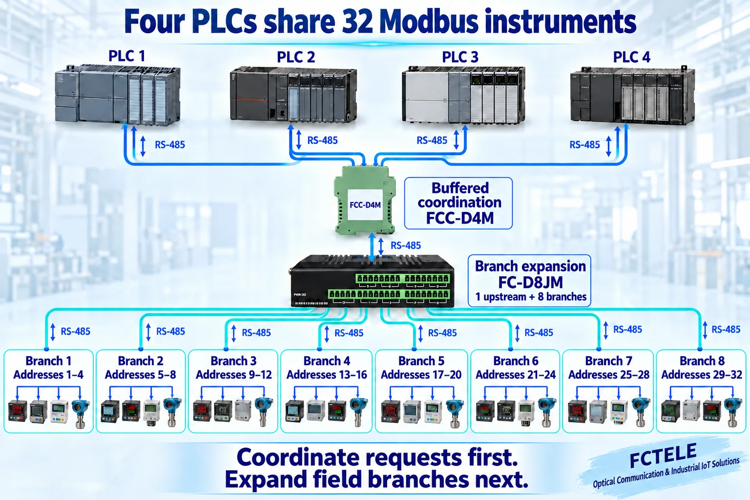
Production, energy-management and monitoring systems share the field instruments. Eight branches with four slaves each use addresses 1–32. Adding readers still requires checking the load on the shared downstream port.
Addresses 1–4Branch 2
Addresses 5–8Branch 3
Addresses 9–12Branch 4
Addresses 13–16Branch 5
Addresses 17–20Branch 6
Addresses 21–24Branch 7
Addresses 25–28Branch 8
Addresses 29–32
Case 3: 2 PLCs + 16 branches, 48 slaves
FCC-D2M + FC-041719-16: 16 branches × 3 instruments = 48 slaves, addresses 1–48.
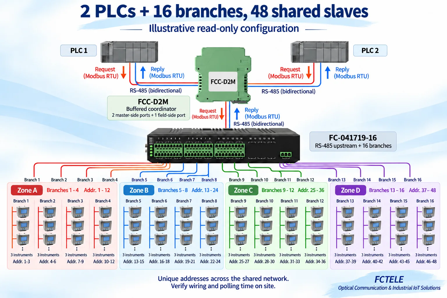
Two reading systems access equipment spread across more field areas. Sixteen branches with three slaves each can be grouped into four zones. More branches simplify wiring; they do not make polling intrinsically faster.
Addresses 1–3Branch 2
Addresses 4–6Branch 3
Addresses 7–9Branch 4
Addresses 10–12Branch 5
Addresses 13–15Branch 6
Addresses 16–18Branch 7
Addresses 19–21Branch 8
Addresses 22–24Branch 9
Addresses 25–27Branch 10
Addresses 28–30Branch 11
Addresses 31–33Branch 12
Addresses 34–36Branch 13
Addresses 37–39Branch 14
Addresses 40–42Branch 15
Addresses 43–45Branch 16
Addresses 46–48
Case 4: 4 PLCs + 16 branches, 64 slaves
FCC-D4M + FC-041719-16: 16 branches × 4 instruments = 64 slaves, addresses 1–64.
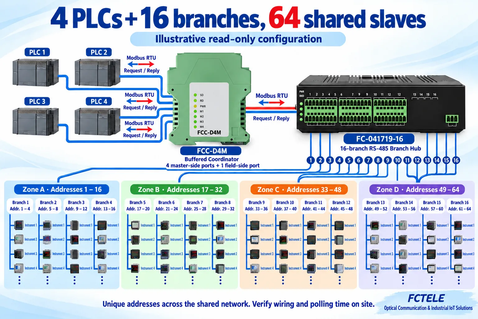
Several reading systems share a larger set of instruments. Sixteen branches with four slaves each use addresses 1–64. Organize register blocks and polling periods before allowing four PLCs to issue repeated high-frequency reads.
Addresses 1–4Branch 2
Addresses 5–8Branch 3
Addresses 9–12Branch 4
Addresses 13–16Branch 5
Addresses 17–20Branch 6
Addresses 21–24Branch 7
Addresses 25–28Branch 8
Addresses 29–32Branch 9
Addresses 33–36Branch 10
Addresses 37–40Branch 11
Addresses 41–44Branch 12
Addresses 45–48Branch 13
Addresses 49–52Branch 14
Addresses 53–56Branch 15
Addresses 57–60Branch 16
Addresses 61–64
Case 5: 2 PLCs + 24 branches, 48 slaves
FCC-D2M + FC-041719-24: 24 branches × 2 instruments = 48 slaves, addresses 1–48.
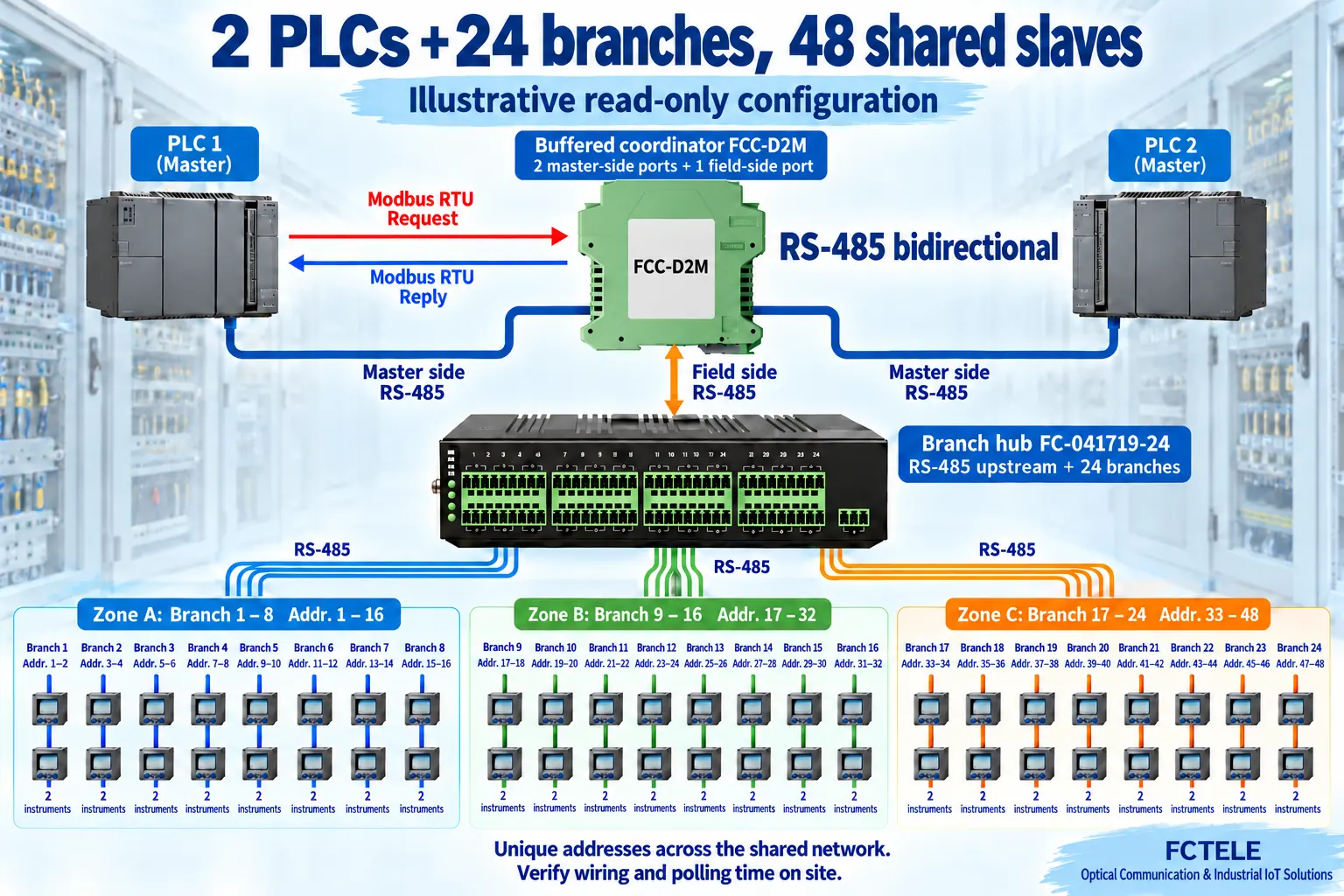
Instruments are distributed across many cabinets, with relatively few nodes per cabinet. Twenty-four branches with two slaves each use addresses 1–48. Compared with the 16-branch, 48-slave example, the main difference is physical distribution.
Addresses 1–2Branch 2
Addresses 3–4Branch 3
Addresses 5–6Branch 4
Addresses 7–8Branch 5
Addresses 9–10Branch 6
Addresses 11–12Branch 7
Addresses 13–14Branch 8
Addresses 15–16Branch 9
Addresses 17–18Branch 10
Addresses 19–20Branch 11
Addresses 21–22Branch 12
Addresses 23–24Branch 13
Addresses 25–26Branch 14
Addresses 27–28Branch 15
Addresses 29–30Branch 16
Addresses 31–32Branch 17
Addresses 33–34Branch 18
Addresses 35–36Branch 19
Addresses 37–38Branch 20
Addresses 39–40Branch 21
Addresses 41–42Branch 22
Addresses 43–44Branch 23
Addresses 45–46Branch 24
Addresses 47–48
Case 6: 4 PLCs + 24 branches, 72 slaves
FCC-D4M + FC-041719-24: 24 branches × 3 instruments = 72 slaves, addresses 1–72.
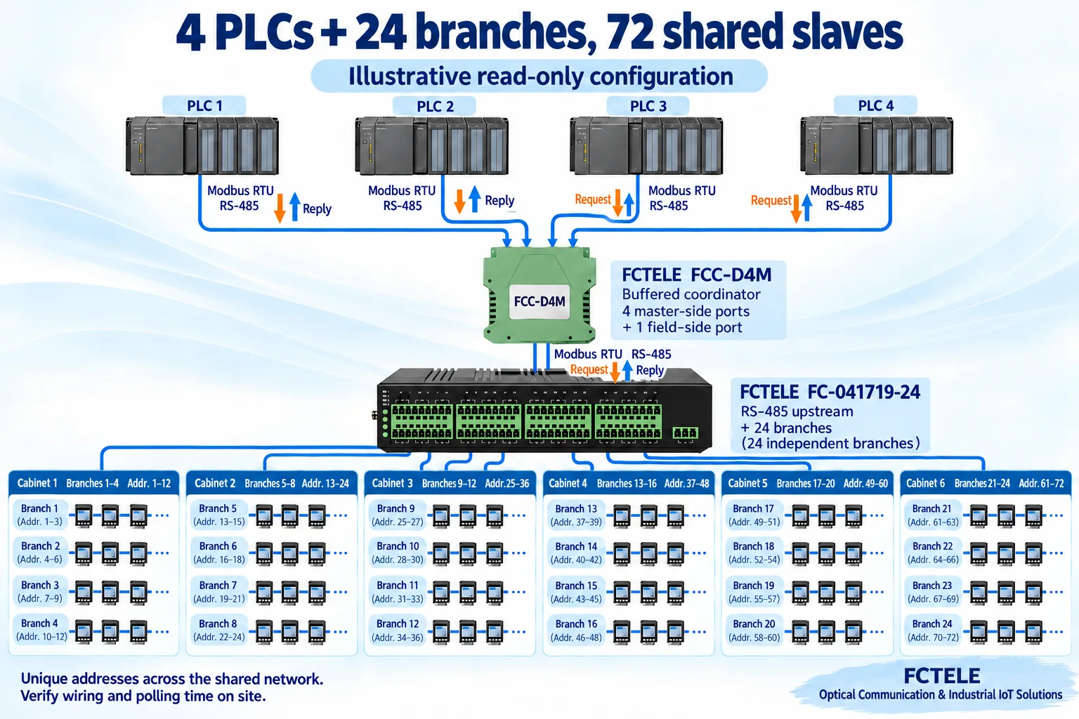
A shared acquisition arrangement spans multiple workshop areas. Twenty-four branches with three slaves each use addresses 1–72 and can be recorded as six zones. With more nodes, offline-device timeouts and the total polling cycle especially need measurement.
Addresses 1–3Branch 2
Addresses 4–6Branch 3
Addresses 7–9Branch 4
Addresses 10–12Branch 5
Addresses 13–15Branch 6
Addresses 16–18Branch 7
Addresses 19–21Branch 8
Addresses 22–24Branch 9
Addresses 25–27Branch 10
Addresses 28–30Branch 11
Addresses 31–33Branch 12
Addresses 34–36Branch 13
Addresses 37–39Branch 14
Addresses 40–42Branch 15
Addresses 43–45Branch 16
Addresses 46–48Branch 17
Addresses 49–51Branch 18
Addresses 52–54Branch 19
Addresses 55–57Branch 20
Addresses 58–60Branch 21
Addresses 61–63Branch 22
Addresses 64–66Branch 23
Addresses 67–69Branch 24
Addresses 70–72
Product roles and supporting information
| Model / product information | Interfaces | Role in this solution |
|---|---|---|
| FCC-D2M | 2 master-side ports + 1 field-side port | Coordinates requests from 2 PLCs |
| FCC-D4M | 4 master-side ports + 1 field-side port | Coordinates requests from 4 PLCs |
| FC-D8JM | 1 RS-485 upstream port + 8 branches | Branch expansion, per-channel short-circuit detection and isolation |
| FC-041719-16 | 1 RS-485 upstream port + 16 branches | Distributed field wiring; check the rate for the selected filtering mode |
| FC-041719-24 | 1 RS-485 upstream port + 24 branches | Additional wiring branches; confirm this model’s protection specifications |
Some older paragraphs on the 16- and 24-channel product pages retain references to “8 channels” or give inconsistent supply ranges. This solution does not rely on those conflicting parameters. Confirm actual ports, power requirements and terminal wiring against the specification supplied with the delivered version.
4. The practical benefits are in retrofit work and maintenance
First, the existing instrument interfaces can remain in service. Each PLC continues reading through its own serial port using Modbus RTU. Adding another reader does not, by itself, require replacing every instrument with an Ethernet device or adding a separate measurement circuit. A new PLC can use an available master-side port with the agreed settings. Requirements beyond two or four PLCs need a new design; do not simply parallel more masters onto the wiring.
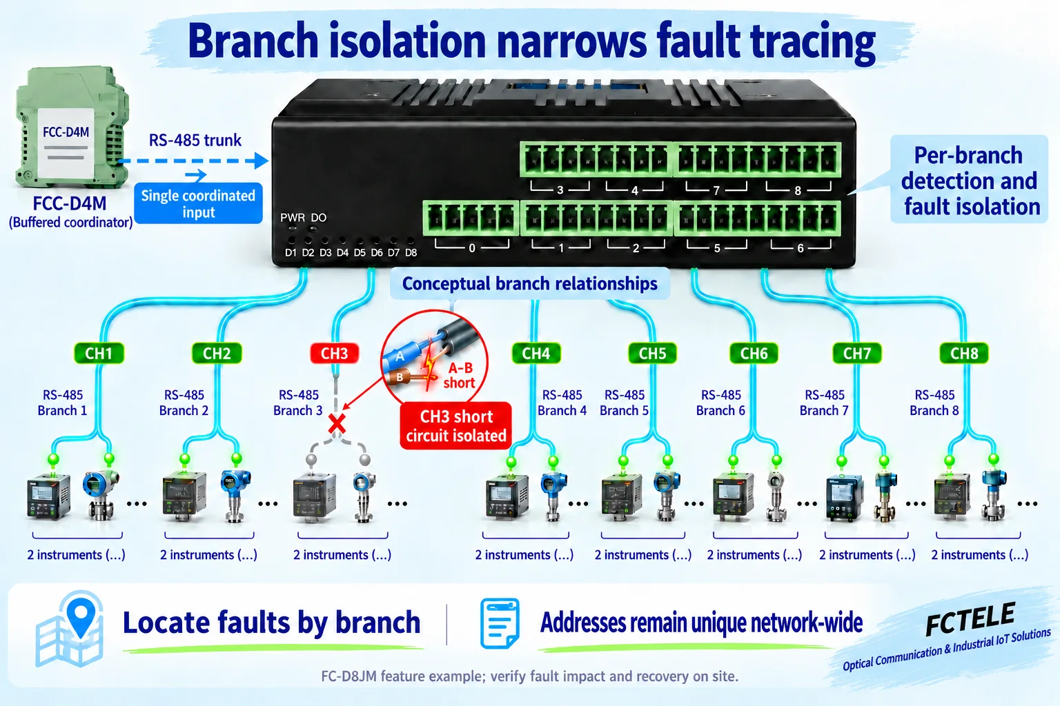
Second, the wiring and equipment responsibilities become clearer. The first stage manages access from multiple PLCs; the second divides the field by workshop, floor or cabinet. Maintenance staff can trace a fault by branch. Published FC-D8JM information specifically lists per-channel A–B short-circuit detection, automatic isolation of a faulty channel, independently isolated power and status indicators. These functions can narrow the troubleshooting area. Check the 16- and 24-channel models separately instead of assuming they inherit every detection feature of the 8-channel model.
For a system integrator, the two-stage arrangement also supports staged commissioning: validate one PLC and one slave, then verify multi-PLC coordination, and finally add field branches one at a time. When more instruments are added later, the address list, branch schedule and PLC program can remain aligned. This is easier to manage than mixing all equipment on one long, undifferentiated bus.
5. Concurrent access does not multiply throughput
Buffered coordination allows PLCs to submit requests concurrently, but the shared downstream port remains a serial communication channel. Each transaction still needs request transmission, slave processing, reply transmission and the necessary gaps. A buffer can absorb some overlap between requests; it cannot remove those intervals. Buffer capacity is also finite. Sustained overload can still increase queuing and timeout risk.
For example, if four PLCs each read one data block from each of 32 slaves, a round can involve 128 transactions. As a budgeting illustration only, assume a complete transaction averages 40 milliseconds and temporarily ignore other overheads. The accumulated time is already about 5.12 seconds. This is not a measured result for any model. Waiting for offline slaves, retries, different frame lengths and PLC program timing can extend the cycle further.
Set polling frequency according to the importance of the data. Combine reads of contiguous registers on the same device, and avoid having every PLC continuously reread the same data at maximum speed. PLC timeouts must cover actual queuing and slave response time and must be commissioned together with the coordinator’s waiting and retry behavior. Different PLCs can receive different values when their reads occur at different times. Synchronized snapshots or fast closed-loop control require an acquisition architecture designed for those requirements.
6. Wiring, configuration and acceptance testing
Start with a device schedule recording each slave’s unique address, serial format, read function code, starting register, block length, byte order and required refresh period. Even when two PLCs read the same address, verify the register definitions item by item. Successful communication does not prove that the decoded engineering value is correct.
Select multi-master mode on the buffered device according to its manual and identify the master-side and field-side ports. Settings used by the configuration tool when entering setup mode must not be copied blindly into the operating configuration. Select the RS-485 upstream version of the branch hub. Baud rate, parity and stop bits must match throughout the shared field segment and its slaves. Published information for the 16- and 24-channel units specifies up to 38,400 bps when digital filtering is enabled. Do not configure solely from the higher rate available with filtering disabled.
Check A/B and signal-reference connections against the supplied terminal definitions and use suitable twisted-pair cable. Check termination, biasing and grounding separately for each electrical segment. If termination is built into a device, do not indiscriminately add more resistors. Supply voltage and accessories depend on the delivered version. Isolation and surge ratings do not mean that mains voltage may be applied to a communication port.
During acceptance testing, let different PLCs read different slaves, then have them request the same slave concurrently. Check the values, initiating PLC and return port, and record maximum waiting time under normal and heavy load. Next, simulate one offline slave, a late reply and a branch fault, and observe the actual effect on other traffic. Begin with read-only operation. If several PLCs will write the same register, separately define control ownership and interlocks: orderly communication alone does not prevent conflicting control commands.
Field questions
Can one buffered hub serve dozens of slaves?
In this confirmed arrangement, the multi-master coordinator connects to a downstream single-master, multiple-slave branch hub, which connects to multiple uniquely addressed Modbus RTU slaves. A port does not necessarily mean only one instrument. The final device count still depends on addressing, electrical loading, wiring and polling-cycle requirements.
Why cannot each branch reuse the same slave addresses?
An ordinary 8-, 16- or 24-branch hub is not a set of independent Modbus routers. A request can be forwarded to several branches. Slaves with duplicate addresses can therefore reply simultaneously, so addresses must be allocated across the whole shared network.
Will several PLCs read the same register at exactly the same instant?
This arrangement does not guarantee that. Requests execute as successive transactions, and a slave’s data can change between reads. A communication buffer is not a data snapshot with a common timestamp. If synchronized data is required, design for it in the acquisition architecture and application layer.
Sources and application limits
The general request/reply and addressing principles follow the Modbus Organization’s Modbus over Serial Line Specification and Implementation Guide V1.02. Product-specific information comes from the FCTELE buffered 2/4-master RS-485 hub user manual (Chinese) and the product information linked above. FCTELE has confirmed the two-stage cascade and routing of replies to the requesting PLC for this solution. The polling example is a planning illustration, not a substitute for site testing.
The illustrations use FCTELE product photographs as appearance references, with AI-assisted topology and communication explanations. Lines do not define terminal pinouts, and the generic PLCs and instruments do not imply certification of compatibility with a particular brand. Confirm acquisition scope, function codes, frame length, late-reply handling, queuing and fault recovery for the actual firmware and project.
Related reading: RS-485 hubs and industrial Ethernet switches: different jobs in a network; Modbus RTU/TCP gateway conversion and response timing.
For selection support, contact FCTELE with the PLC count, slave list, branch distribution, serial format, register ranges and desired refresh period. These details help confirm both stages of equipment and suitable timeout settings.
English translation of the FCTELE Chinese technical article: Multi-PLC Modbus hub solution — original Chinese article. The Chinese source was published on November 2, 2026.
