


POE POWER MAINTENANCE
How the port decides to keep supplying power
The powered device presents an electrical signature after startup. During standby it may briefly draw more current to satisfy the maintain condition. Follow the DC path, observe current over time, and compare supply and link changes before attributing an outage to MPS.
Supply
A DC loop powers the endpoint on the Ethernet cable.
Observe
Pulsed current can satisfy the maintain condition in standby.
Compare
Compare the order of supply and link changes.
Record the exact PSE, PD and power mode.
Use suitable equipment to capture transient current.
Compare sleep, power removal and link transitions.
Selection and verification checklist — expand
| Check | What to confirm | How to verify |
|---|---|---|
| Startup | Detection and power-up | Review the port state |
| Standby | Current at the interface | Capture pulse width and spacing |
| Recovery | Power, link and application | Align event timestamps |
An industrial switch can power an endpoint and exchange data over the same Ethernet cable. When the endpoint enters a low-power state, the port still has to determine whether to keep supplying it. The electrical behavior that the powered device presents during operation is called the maintain power signature, or MPS. To understand it, follow the power switch, the sampling and timing logic, and the data link separately. Each provides different evidence when an endpoint repeatedly restarts after entering standby.
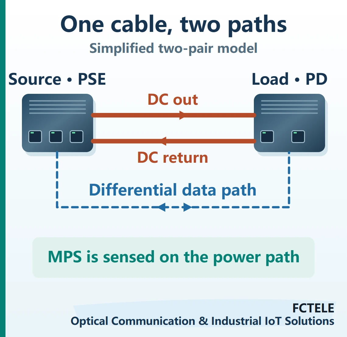
Two things to observe on one cable
FCTELE lists a PoE+ option for its managed ring switch with eight Gigabit copper ports and two Gigabit fiber ports. In the power system the switch is the power sourcing equipment, or PSE. A camera, access point, or sensor terminal at the other end is the powered device, or PD. Consult the documentation for the actual ordered version, power supply and status fields.
A simplified isolation transformer model helps explain the two paths. The Ethernet transceiver produces a differential signal across the two conductors of a pair. The receiver observes the difference between them. The power circuit uses center taps on the magnetics to establish a DC path between the sets of pairs involved in power delivery. One powered pair carries the outgoing current and another carries the return. The arrangement depends on the equipment and PoE type. The current arrows in the figure represent this loop. Bidirectional data exchange follows its own signal path. At the endpoint, the power interface feeds a DC converter, which supplies internal loads.
This separation gives the port two sets of evidence. Network observations include link state and frame or traffic counters. Power observations include port voltage, input current and power state. Current can still flow when the endpoint stops sending traffic. After port power is removed, stored energy in the endpoint may keep its processor running briefly, so the link can go down later. Put these events on the same time axis during diagnosis.
Initial detection and confirmation after power-up
On first connection, a standard PoE source applies its detection conditions and checks the PD detection signature. Once the relevant conditions are met, the port determines power capability by its supported method and proceeds with power-up. Detection takes place before normal operating voltage is available. After power-up, the PD interface and load are in a different electrical state, and the PSE begins monitoring the signature used to maintain power.
Calling both signatures an online indication hides an important diagnostic distinction. If the port stays in detection, investigate the connection, compatibility and configuration. If the device starts and then loses power after entering a particular operating state, first establish the sequence. Then investigate power maintenance, load overcurrent, port settings or a fluctuation in the input supply. Some management interfaces summarize several states with a single indicator, which serves as a starting point for the investigation.
The power and data interfaces continue to evaluate their own conditions while Ethernet frames are flowing. The MPS is expressed through electrical behavior at the port. Packet counters provide no direct reading of those current characteristics. A continuous power supply likewise gives no assurance that traffic reaches its destination. Verify both a stable power path through the cable and the arrival of traffic at the intended port.
How a low-power endpoint keeps the supply on
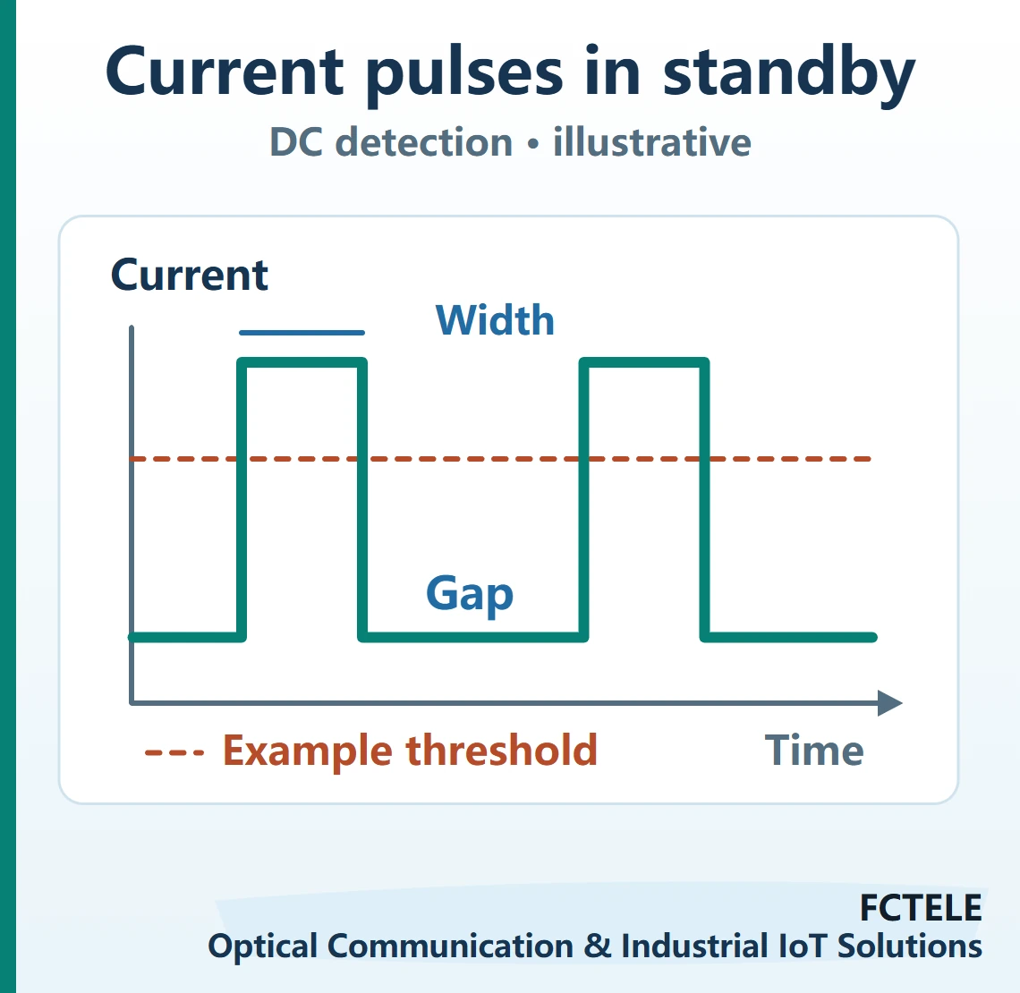
During normal operation, the input current may already satisfy the DC maintain condition. In sleep mode the main load switches off and a small group of functions, such as the wake-up circuit, stays active. Current on the cable falls. A PD interface that supports pulsed MPS can briefly draw extra current at suitable intervals, allowing the PSE to detect adequate current for the required duration in its observation window. The powered interface controls that added draw. The application does not have to send a message for each pulse.
Picture a stepped waveform with gaps. The tops represent periods of extra current, and the lower level represents standby draw. Detection depends on the pulse height, its duration and the time between pulses. A low average current alone gives no basis for declaring the signature absent. If sampling or input filtering makes the observed pulse too narrow, the average shown on a meter can still appear plausible. Evaluate the waveform as observed at the port.
Some earlier PSEs can use AC impedance to assess whether the device remains connected. The waveform here focuses on DC detection. Thresholds, timing and loading conditions depend on generation, PoE type and detection method. Use the applicable specification and device documentation. The sleep pulses in TI’s application note illustrate a particular PD chip implementation. Consult the actual FCTELE product documentation for implementation details and event reporting.
How an observation becomes a power-switch action
Think of DC detection as a repeating state check. A sensing stage in the port power path obtains current information. The controller uses its detection method to see whether an acceptable signature appears in time. After an acceptable signature it keeps the supply on. When the signature remains absent for the applicable disconnect period, the controller removes port power and returns to detection or waits according to its policy.
Physical removal is a typical case the mechanism handles. Unplugging the cable opens the power loop and current stops flowing through the original load. The endpoint need not send a farewell message. A different case arises when a connected PD presents an inadequate standby signature. Both cases can end in removal of power. Distinguish them using the connection state, port events and reproducible device behavior.
Measurement location matters. The DC converter, input capacitance and energy storage circuits on the PD side can change local current waveforms. The port decides from the quantity it observes at its power interface. A current measurement on one internal low-voltage rail cannot directly establish the waveform on the Ethernet cable. A multimeter can check steady values, while pulse spacing and the order of disconnect events require equipment suitable for transient capture.
Use the timeline to identify the first change
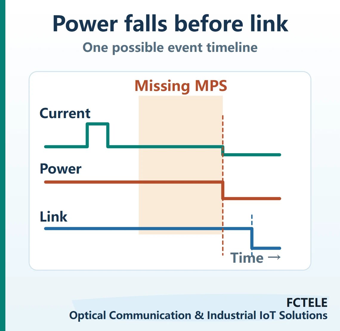
Suppose an endpoint operates normally, goes offline after entering sleep and then returns through its startup sequence. Record the times of sleep entry, power removal, link change and application reconnection. If power falls first and the device restarts immediately afterwards, start by investigating the supply. If port power remains on and only link negotiation or traffic counters change, examine the cable data path, the device’s network state and application reconnection.
Narrow down the power evidence. If multiple ports change at the same time, start with shared input power, the total power budget and management policy. If the issue follows a particular low-power transition, compare the endpoint sleep event, the port’s reported shutdown reason and the interface current record to evaluate the MPS hypothesis. If power disappears when an infrared illuminator, motor or heater starts, instead investigate voltage sag, current limiting and total power budget as the load increases. Each event can cause the same offline indication even though it starts at a different point.
Record time resolution, measurement points and configuration. A management system that polls once per second can give two closely spaced events the same timestamp. Mark the sequence as undetermined and capture it with more suitable observations. The waveform and spacing in the figure illustrate relationships and do not supply measured values or manufacturer specifications.
Acceptance covers the entire standby cycle
Where possible, compare a known compatible PSE and PD in an isolated test environment and document port settings and cable conditions. Record initial startup, normal traffic, entry into low power, stable standby and wake-up recovery. After reproducing the behavior, change one variable at a time. Examples include replacing the jumper with a short cable, using a verified port of the same type, or switching sleep modes where the endpoint permits it. This helps determine whether the behavior follows the endpoint, cable, port or a shared condition.
The record should establish whether power continued at the interface, what stage the endpoint was in and whether real traffic resumed. Successful power-up covers startup. The standby and wake records cover ongoing operation, and the port’s reaction to unplugging checks disconnect detection. Logging the three separately helps explain why a system can work during the day and fail during a period of lower load.
Sources and scope
FCTELE managed ring switch product page (Chinese) · TI SLVA588 application note on sleep-mode MPS · TI TPS23730 datasheet, section 8.4.6. The illustrations describe general power paths. Consult the exact ordered model for implementation details.
Translated from the Chinese technical article: Read the original Chinese article.
Common questions
Can a PoE port stay powered with no traffic?
Yes. MPS is detected electrically at the power interface. The port can stay powered while application traffic is idle if its maintain conditions are met.
Does a low average standby current prove the MPS is missing?
Check pulse amplitude, duration and spacing at the interface. A multimeter average can hide transient behavior.
What should I check first when a sleeping endpoint goes offline?
Align port power state, endpoint sleep events and link changes. If power goes first, investigate the signature, overcurrent, input power and port policy.
Further reading
Standard PoE detection and compatibility · PoE energy use and scheduled power
