


CLASSICAL CAN BIT STUFFING
How a receiver separates payload from stuff bits
Within the stuffing region, the transmitter inserts an opposite bit after five equal wire bits. The receiver checks and removes that bit before interpreting the fields. Start with the frame boundary, then compare the wire trace with the decoded frame.
Insert
The transmitter inserts an opposite bit after five equal wire bits.
Find the boundary
The receiver stops applying dynamic stuffing after the CRC sequence.
Probe both ends
Compare the same test frame on the two copper segments.
Identify Classical CAN, frame type and nominal bit rate.
Check whether the run lies within the stuffing region.
Match raw transitions to the analyzer frame and controller errors.
Trace verification checklist — expand
| Check | What to confirm | How to verify |
|---|---|---|
| Wire bits | Run of equal states | Count from the start of the applicable region |
| Field boundary | End of the CRC sequence | Identify the delimiter, ACK and EOF |
| Fiber extension | Location of the observation | Align the two copper captures |
After writing CAN data into a controller, you may see more bits on an oscilloscope than the sum of the logical frame fields suggests. Bit stuffing accounts for those extra bits. Within the applicable region of a Classical CAN frame, the transmitter inserts an opposite bit after five consecutive bits of the same value. The receiver identifies and removes that bit using the same rule, then interprets the original fields. This process helps receivers correct bit timing and explains why equally long messages can occupy the bus for different amounts of time.
A flat signal still carries bits
On a high-speed CAN copper bus, the transceiver turns controller bits into differential states across CAN_H and CAN_L. A dominant bit represents logical 0 and a recessive bit represents logical 1. When a node drives the dominant state, it can override recessive states sent by other nodes. While the electrical state stays constant, the receiving controller still makes a decision at its sample point in each bit time. A dominant plateau can contain several zeros, each occupying a bit time.
Each node has its own oscillator. The nominal bit time can be set to the same value, with small deviations remaining in practice. The receiver aligns its timing at the start of the frame and uses qualifying edges to correct phase within the frame. Without a suitable edge for a long period, the offset between the receiver’s sampling and the transmitter’s bit boundaries grows. Stuffing creates transitions within long runs, providing opportunities for synchronization. Correct sampling also depends on propagation delay, sample point settings, and signal quality.
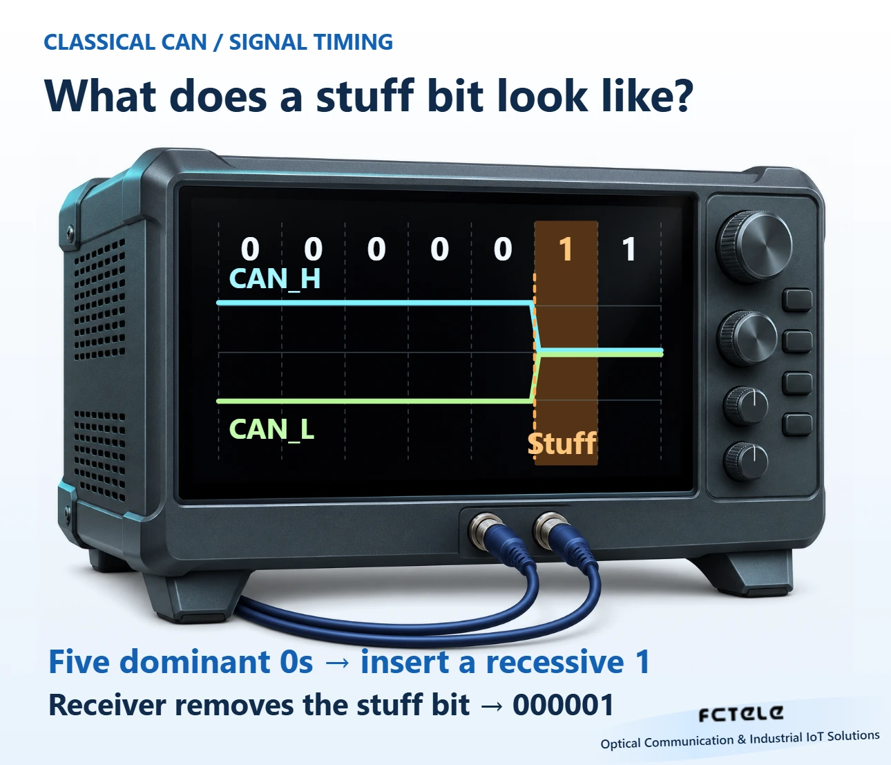
The transmitter counts bits already sent on the bus
Consider a simplified sequence within the dynamic stuffing region, starting with a run count of zero. The logical sequence calls for five zeros followed by a one. After sending the fifth zero, the transmitter inserts a one and then sends the original one. The bus carries five zeros, a stuff one, and the original one. The insertion can fall within a byte or just after the end of a field. The controller tracks a continuous bit stream and carries the count across byte boundaries.
The inserted bit is itself part of the transmitted sequence and starts a new run. Suppose the original sequence calls for four ones after the five zeros. Those four ones and the inserted one form five consecutive ones, so the transmitter then inserts a zero. The rule cannot be reduced to one insertion for every five original bits. Neighboring fields and earlier inserted bits affect when the next insertion occurs.
After five identical bits, the receiver expects the next bit to have the opposite state. When it samples the expected value, it recognizes the stuff bit and updates its state for the received run, while withholding that bit from field parsing. The following original one is retained. The two ones can appear as one continuous plateau on the bus. The receiver distinguishes their roles from their position and the run history.
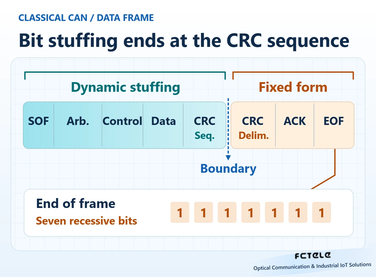
Where the run count stops
Dynamic stuffing also applies to the eligible fields of a Classical CAN remote frame. Its DLC can indicate the requested data length, but the frame has no data field. When checking a trace by hand, identify the frame type before locating the CRC sequence. Treating the remote frame DLC as a count of data bytes that follow would shift all subsequent boundaries.
For a Classical CAN data frame, dynamic stuffing begins at start of frame and applies through the arbitration, control, and data fields to the end of the CRC sequence. The receiver tracks field lengths as it processes this region. Stuff bits add time on the bus. The data length code, or DLC, keeps its original meaning. The logical layout of the fields can differ from the physical time divisions seen on an oscilloscope.
The CRC delimiter, ACK field, and end of frame follow their own rules after the CRC sequence. The earlier dynamic stuffing count no longer applies. For example, a Classical CAN end of frame contains seven consecutive recessive bits. This run alone does not indicate a stuff error. Locate the frame boundary and any error flags before deciding which region contains a plateau.
The transmitter calculates the Classical CAN CRC sequence from the unstuffed logical bits from start of frame to the end of the data field. It then includes the CRC sequence in the region subject to stuffing during transmission. The receiver removes dynamic stuff bits and performs the corresponding CRC check. The encoding overhead and the field integrity check therefore serve separate purposes. CAN FD uses different rules in its CRC field. Verify the frame format and controller configuration against the applicable specification.
Equal data lengths can occupy different amounts of time
Separate frame transmission time from the time a message waits to transmit. Stuffing affects the wire time of the frame itself. Arbitration delay depends on what other nodes are sending at the time. For a periodic message, record the interval between successive start-of-frame bits separately from the duration between the start and end of one frame. Changes in the two measurements point to different causes.
Consider two successfully transmitted Classical CAN data frames with the same number of data bytes. Their identifiers or data patterns can differ. One frame may contain repeated long runs, while zeros and ones often alternate in the other. The first may need more stuff bits, and the particular values in the CRC sequence also affect the count. At the same nominal bit rate, each stuff bit adds one bit time. Use an observed or conservative on-wire length for load estimates.
A protocol analyzer usually displays the identifier, DLC, and recovered data in its decoded view. To check bus occupancy, establish where measurement begins and ends. A frame’s transmission time, the wait from queuing to successful arbitration, and time spent retransmitting after an error are different quantities. Documenting the boundaries keeps increased frame length separate from contention delay.
Locate the region where a stuff error appears
Within a dynamically stuffed field, the receiver reports a stuff error if it samples a sixth bit of the same value where an opposite bit should appear. A long plateau can come from abnormal behavior at the transmitting side or from local sample point settings, bit rate, or signal distortion. If an error-active node sends an active error flag, other nodes can subsequently see a long dominant run that violates the rule. A stuff error in one log can therefore be the result of an earlier error.
Record error types, the earliest event, and any available waveform. A CRC error indicates a mismatch between the receiver’s calculation and the received CRC sequence. A form error involves a field with a prescribed format. An ACK error means the sender did not observe the expected dominant acknowledgement in the ACK slot. These errors can follow one another during the same incident. Sorting events by time and checking the affected field helps narrow the investigation.
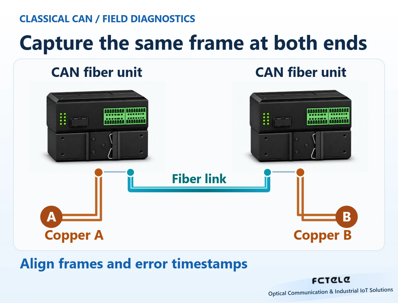
Check each copper segment and device role when extending CAN over fiber
FCTELE’s product documentation for its eight-channel DIN-rail CAN fiber modem lists CAN-to-fiber repeating and point-to-point operation. In an engineering test, list the CAN copper segments, fiber, and end devices as separate observation points. Verify the frame format, bit rate, termination, and wiring against the actual device documents. Then use a known message in an isolated test setup to check reception at each end. The figures identify observation points. Consult the documentation for the relevant model to determine how it transfers signals across the fiber.
If the signal and decoded frames remain stable on the transmitter-side copper segment but intermittent errors appear near the receiver, compare the other end’s state and timestamps. Check whether the fault follows a cable, end device, or particular load. Keep the message period and other conditions traceable and adjust one variable at a time. The final record should show whether fields were recovered correctly, whether the errors recurred, and whether real application traffic recovered after changing the path. This separates ordinary stuffing overhead from actual transmission faults.
Sources and scope
Bosch: Error detection in CAN and CAN FD · Microchip: CAN bit stuffing and frame format · FCTEL DIN-rail eight-channel CAN fiber unit (Chinese)
Translated from the Chinese technical article: Read the original Chinese article.
Common questions
Why insert a bit after five equal bits?
The opposite bit creates a transition on the wire. Edges that meet the synchronization conditions can be used to adjust bit timing, limiting the duration of a transition-free run.
Do the seven recessive EOF bits cause a stuff error?
Classical CAN EOF has a fixed form. Its seven recessive bits are outside the region subject to dynamic bit stuffing.
How can I trace a stuff error across a fiber link?
Capture the same test frame on both copper segments, verify the bit rate, sampling and termination, align the controller error timestamps, and check how the fiber units forward traffic.
Further reading
Extending a CAN bus with fiber · Electrical interfaces and CAN arbitration
