

Application scheme of Fctel technology industrial switch series products in power industry
A power network has to move many different kinds of information: meter readings, protection and control status, alarms, maintenance traffic and, in some locations, video. The communications design must account for more than bandwidth. It must also match the installed interfaces, fiber routes, available power, operating environment and the way technicians will diagnose a fault years later. This article presents a practical reference architecture for using published FCTEL industrial Ethernet switches in substations, distribution sites and wind generation. It is a design guide, not a claim that every product is interchangeable or that one topology fits every grid.
Start with the signals and the operating site
Before drawing a ring or choosing a switch, list every endpoint. A substation may contain intelligent electronic devices, meters, remote terminal units, engineering laptops, cameras and a gateway to the control center. Some are Ethernet devices; others expose serial or application-specific interfaces and need a suitable gateway. Record the physical port, speed, connector, protocol, expected traffic and whether the device needs its own network segment. A switch forwards Ethernet frames; it does not by itself translate a serial protocol into Ethernet.
Then map the sites. Note the distance between cabinets, whether existing fiber is single-mode or multimode, how many strands are available, and whether the route has physically diverse paths. Document cabinet temperature, electromagnetic exposure, mounting space, grounding, the available DC supply and the required maintenance window. These details often decide the equipment choice sooner than a headline port count. A product with enough RJ45 ports can still be the wrong choice if the optical uplink, power input or management method does not match the installation.
The resulting schedule should identify which connections stay within one cabinet, which cross a building or substation yard, and which leave the site. Keep the control, monitoring and engineering paths visible in the design. This makes it easier to size uplinks, apply access rules and explain the network to operations staff.
Match a published FCTEL model to each network role
FCTEL's public catalogue provides managed DIN-rail switches with different copper and SFP combinations. The FCM-G4Q2 is listed as a managed model with four Gigabit copper ports and two optical uplinks. It is a possible starting point for a smaller field cabinet with a few Ethernet devices. The FCM-G8Q2 provides eight Gigabit copper ports and two Gigabit SFP positions for a cabinet with more local endpoints. Where the design calls for more optical connections, the published FCM-G8Q4 lists eight Gigabit copper ports and four 1G SFP positions.
These models illustrate roles; they are not a bill of materials. Verify the exact product revision, port mapping, supported SFP types, input power and required management functions before ordering. If the site needs a high-density aggregation switch, a rackmount product may be more appropriate than a DIN-rail unit, but its optical density, mounting and power arrangements need a separate review. If the site has serial-only equipment, specify an appropriate serial server or protocol converter as a separate item rather than assuming an Ethernet switch provides conversion.
The public pages for the FCM-G8Q2 and FCM-G8Q4 describe managed functions including VLAN, QoS and ring-related protocols. That gives a design team options for separating traffic and planning path resilience, but the final settings should be tested on the selected hardware and firmware. Avoid copying a protocol label from one product page into a general specification for the entire range.
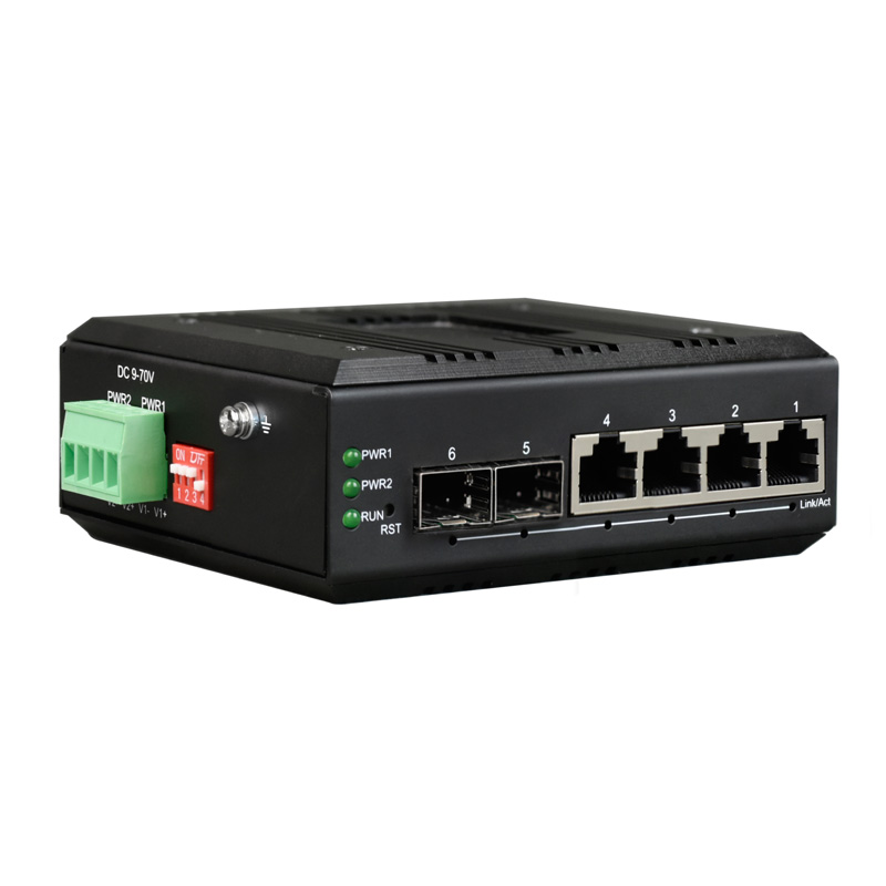 FCM-G4Q2
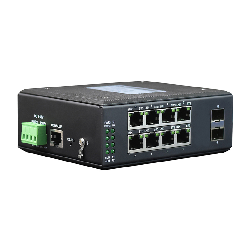 FCM-G8Q2
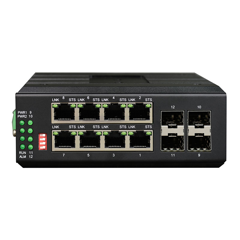 FCM-G8Q4
Choose the fiber topology for the failure you need to survive
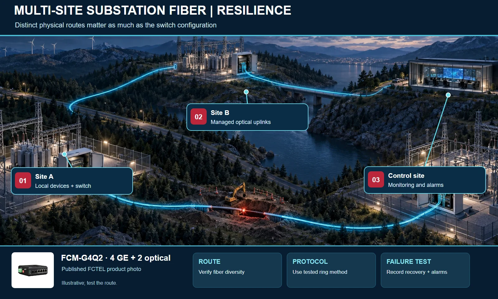
A simple line topology can be efficient when sites follow one physical route and a break can be accepted until repair. A star is often straightforward to maintain when each remote cabinet has a dedicated path to a control room. A ring offers an alternate route, but only if the fiber is routed meaningfully, the switches support the chosen redundancy method, and the configuration is tested. A logical ring laid over one shared duct does not protect against the duct being cut. Redundancy also requires attention to power: two network directions cannot help if all nodes depend on the same unprotected supply.
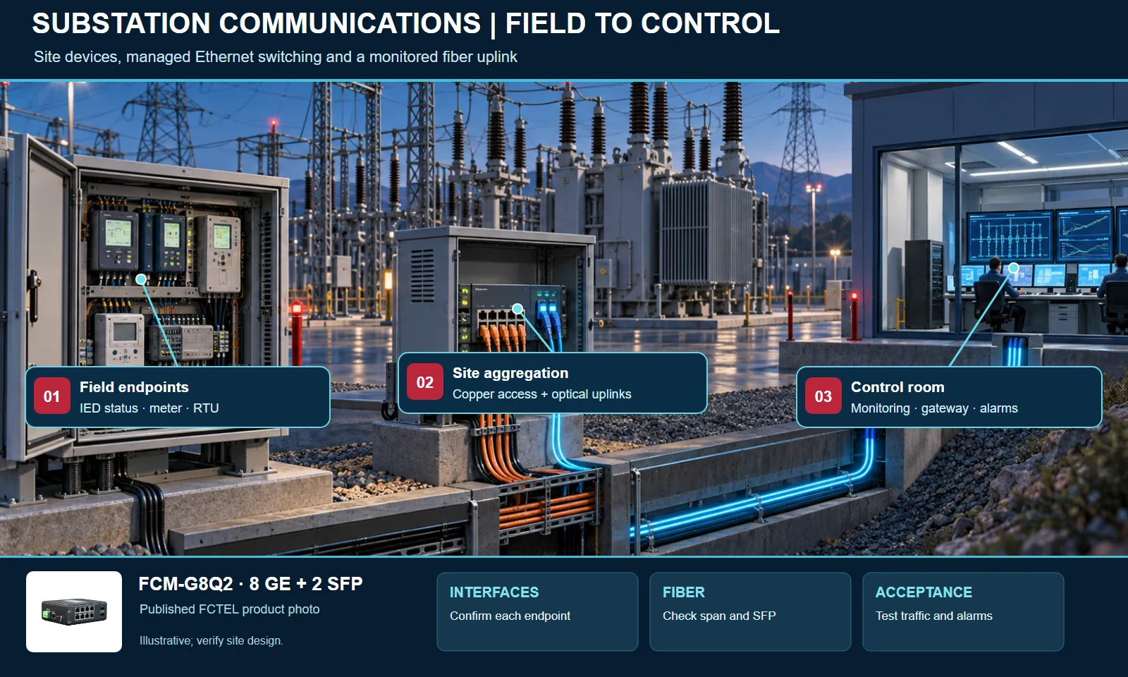
For a substation group, consider managed switches at each location, with local copper connections to Ethernet-capable devices and optical uplinks between sites. Place control-room access where operators can see the network status and alarms. Decide which device owns the ring or spanning-tree configuration, how link failures will be reported, and what happens when a switch is replaced. The FCM-G4Q2, G8Q2 and G8Q4 can be evaluated for different site densities; do not force the same model into every cabinet just to make the drawing symmetrical.
RSTP and ERPS are examples of mechanisms described on published FCTEL product pages, but they should not be mixed casually. Select one design approach for the relevant segment, verify every participant's support, and test both the normal and failed path. Record recovery observations from the actual installed configuration. The application scene below illustrates the operating environment; it does not promise a particular recovery time.
Wind generation: extend the same discipline to remote equipment
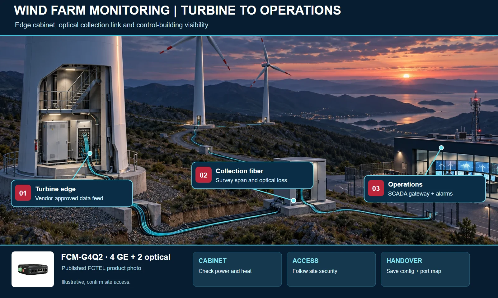
Wind sites add distance, distributed cabinets and access constraints. A turbine may expose controller and monitoring interfaces locally, while a collection network carries selected information toward a control building. Start by confirming what the turbine vendor permits to be connected and whether the switch is installed in an existing protected cabinet or a new enclosure. The optical span, fiber type and transceiver choice should be derived from the actual route, not from the general idea that a turbine is “far away.”
A compact managed switch can aggregate local Ethernet endpoints where its published port count and environmental specifications fit. Fiber then carries the traffic toward an aggregation point or control room. If a ring is proposed, check that each node has two usable optical paths and that the physical routes are sufficiently independent. If those conditions are absent, a carefully documented line may be more honest and maintainable than a ring on paper. For any turbine or substation network, establish who may change switch settings, how configurations are backed up and how field technicians identify the affected segment.
Keep operational technology traffic separated according to the site's security policy. Management access, engineering access and monitoring feeds may have different owners and different consequences when interrupted. VLANs can organize traffic on supported managed switches, but they are only one part of a complete access-control design. Confirm the upstream firewall, gateway and monitoring arrangements with the project owner.
Plan bandwidth, segmentation and maintainability together
For each traffic class, estimate the normal and peak load. Metering and alarm messages may be small, while video or file transfers can change the uplink calculation. Include growth and the possibility that traffic reroutes after a link failure. A Gigabit label on one port does not guarantee that the complete path meets every latency or throughput target. Check port speeds at both ends, SFP capability, optical budget and the capacity of the upstream device.
Where the selected model supports them, VLANs can separate device groups and QoS can prioritize traffic according to the approved network policy. Avoid promising deterministic behavior from a switch feature list alone. End-to-end performance depends on all connected devices, congestion points, the protocol in use and the tested configuration. Use port descriptions, a consistent naming scheme and a current diagram so a technician can identify a cable and its destination without guessing.
Power and grounding deserve the same care as the data path. Verify the accepted voltage range and wiring on the precise model, size the supply for the installed load, and check any redundant input arrangement against the site design. Document surge protection and bonding requirements with the electrical engineer. Label the fiber type, strand assignment and transceiver at both ends. These records can save more time during a fault than an additional unmanaged feature.
For brownfield projects, inspect the existing network before specifying replacements. An older link may use an optical connector, wavelength or serial gateway that is absent from a new switch proposal. Ask whether the operator needs to keep the old supervisory system online during migration. A phased cutover might require spare ports, temporary parallel paths and a rollback procedure. The most useful architecture is one the site team can install without losing visibility of essential equipment.
Specify how faults will be found. A managed switch can expose port and event information, but someone must know where those records are collected and who responds. Agree on device names, management addresses, time synchronization and alarm destinations. If the project owner has cybersecurity rules, incorporate them in the design review; a physically resilient ring still needs controlled administrative access. Include these operational decisions in the acceptance pack rather than leaving them to the next maintenance contractor.
Commissioning: prove the design under normal and fault conditions
Before energizing the network, compare the as-built cabinet with the approved port schedule. Confirm the switch model, hardware revision, power wiring, optical modules and patching. Then bring up links one segment at a time. Record optical receive levels where the equipment and test method permit, check link speed and duplex, and confirm that every endpoint appears where the drawing says it should. A passing link light is a starting signal, not a complete acceptance test.
Next test the intended traffic. Confirm that meters, remote units and supervisory systems exchange the expected data. Check that management access is limited to the right users and that the agreed monitoring station receives alarms. If VLANs or QoS policies are configured, verify them with representative traffic rather than assuming that the configuration file is sufficient evidence. Save the final configuration and note the firmware version, port map, SFP part numbers and contact route for support.
For a redundant design, disconnect each planned path in a controlled test window and observe the behavior. Restore it and check for unexpected loops, alarm persistence or stale routes. Repeat only the tests appropriate for the installed equipment and site procedure. The acceptance record should state what was actually tested, the result, and any remaining limitations. This gives operations staff a reliable baseline for future troubleshooting.
Common questions before specifying a switch
Can one model be used at every power site?
Usually the endpoint count, optical connections, power arrangement and cabinet space differ by location. A small field cabinet may need four copper ports and two optical uplinks, while an aggregation point needs more SFP capacity. Standardizing where it helps maintenance is useful, but it should not replace a site-by-site port and environment review.
Does a ring automatically provide uninterrupted service?
No. A ring needs compatible devices, a configured redundancy protocol, correct fiber connections and an acceptance test. Its behavior during a failure depends on the chosen protocol and implementation. Ask for the required recovery target, then verify it in the real topology. Also examine shared ducts and shared power supplies, which can defeat the purpose of path redundancy.
Can the switch connect directly to a serial RTU or meter?
Only if the equipment already provides a compatible Ethernet interface or a separate converter/gateway is specified. Copper Ethernet ports and SFP uplinks do not translate RS-232 or RS-485 by themselves. Identify the serial standard and application protocol before selecting the gateway and test the complete path.
What information should be sent to FCTEL for a recommendation?
Send the endpoint list, interface types and quantities, fiber type and distance, desired topology, supply voltage, cabinet conditions, management requirements and any existing product models. Mention whether the project is new, an expansion or a replacement. A sketch and a few cabinet photographs can help the technical team identify missing details early.
