


ETHERNET PADDING, AT A GLANCE
Why can a short message appear as a longer frame?
Ethernet may add padding before the FCS to meet its minimum MAC-frame format. The padding is outside an IPv4 packet and should not become application data. Capture software may observe processing before padding or receive a record without the FCS, so its displayed length alone does not prove an undersize transmission. Verify the observation point and length convention.
Build the outer frame
Padding meets the outer format; it does not add application meaning.
Locate the observer
Software may see a different stage from the physical link.
Respect the inner boundary
For IPv4, use the IP total length rather than treating padding as data.
Verify the count
State which headers, tags and FCS bytes the length includes.
Verify the capture
Record direction, offloads, retained length and FCS settings.
Verify the parser
Confirm that the upper-layer length defines valid application content.
Selection and verification checklist — expand
| Check | What to confirm | How to verify |
|---|---|---|
| Frame convention | Headers, tags and FCS | Document the exact start and end of the count. |
| Observation point | Before NIC, wire or receiver | Preserve interface and collection settings. |
| Capture completeness | Original versus retained length | Check truncation and collection limits. |
| Protocol boundary | Valid IP or other protocol length | Inspect the specified length and parser behavior. |
| Fault evidence | Counters, direction and time | Correlate known traffic at both ends. |
Conceptual examples, not to scale, not measurements or claims of a particular product implementation.
A PLC sends a short status message, yet the content transmitted over Ethernet is longer. A capture shows 60 bytes, while documentation describes a 64-byte minimum frame. Do not immediately conclude that a switch removed four bytes. The application message, Ethernet encapsulation and software capture are different layers of observation. Putting padding in the correct place explains the apparent contradiction.

Separate the message, IP packet and Ethernet frame
An application cares about a status, command or measurement, but transmission needs information that network equipment can recognize. Think of the message as a note, the IP packet as its envelope and the Ethernet frame as the outer packaging for this link. The analogy explains layers, not three physical boxes: the wire carries a continuous sequence of bits.
In the ordinary untagged Ethernet example used here, the MAC frame runs from the destination address through the frame check sequence, or FCS. A MAC address identifies a sender or recipient on the link; the FCS helps a receiver check for transmission errors. The preamble precedes the frame, and the interframe gap is idle time between transmissions. Neither is part of this 64-byte count.
The minimum applies to the outer MAC frame, not to the length of every PLC instruction. When reading documentation or captures, first establish where counting begins and ends. Mixing application data, headers and the FCS can make ordinary encapsulation look like extra application content.
Append padding before forming the frame check sequence
If the supplied upper-layer content is too short, Ethernet transmit processing appends padding after that content and before the FCS. It is like protective packing: it takes up space without adding words to the note. Whether software, a driver or hardware performs a particular operation depends on the network interface or embedded implementation.
Consider a deliberately bounded example: an untagged Ethernet header of 14 bytes carries a 28-byte IPv4 packet. That IP packet can consist of an ordinary IPv4 header and a UDP header, with no UDP application payload. Adding 18 padding bytes and a four-byte FCS produces a 64-byte MAC frame. This illustrates the structure; it is not a measurement of a FCTEL device.
The padding is included in the content protected by the Ethernet checksum. It cannot be arbitrarily changed after the FCS is formed. The receiver checks the received frame, not just the application message. No CRC calculation is needed to understand the sequence: form the required frame content, then generate its corresponding check value.
Padding should not become additional application data
For IPv4, the total-length field in the IP header defines the IP packet length, including its header and data but excluding outer Ethernet padding. The receiver passes the IP portion upward for further interpretation. RFC 894 explicitly separates padding from the IP packet and specifies zero-byte padding when needed for the encapsulation it describes.
An upper-layer parser must not treat all remaining captured Ethernet bytes as application content. It should validate its protocol length and boundaries rather than append the outer packing to a command. Nor should it simply delete every trailing zero: zero may be valid data. The protocol, not the visual appearance of a byte, determines the boundary.
Other layer-two protocols need their own encapsulation rules; IPv4 total length cannot be applied mechanically to every protocol. Padding should not carry private control instructions or uninitialized memory. The practical habit is to verify the outer frame boundary and the inner message boundary separately.
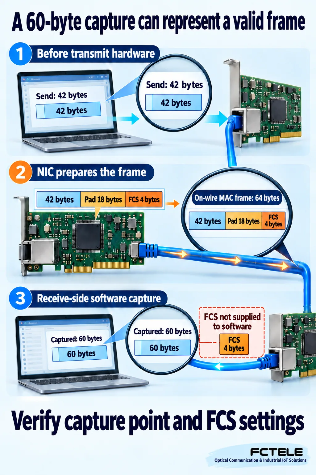
Why software may display 60 bytes or even fewer
Capture software does not necessarily receive the complete wire representation. Many interfaces check the incoming FCS without handing those four bytes to the operating system. Software can therefore record 60 bytes corresponding to a complete 64-byte MAC frame on the wire. Wireshark documentation highlights this distinction: a displayed length of 60 alone does not establish an undersize transmission.
A transmit-side capture can observe another point, before hardware adds padding and the FCS. Its record may be shorter than 60 bytes even though hardware subsequently produces a valid transmitted frame. A sender screen, receiver screen and physical-link observation are different viewpoints. Comparing two displayed lengths alone cannot prove that equipment between them removed content.
Also distinguish original length from captured length. A collector may retain only the beginning of each frame, so not every original byte is necessarily saved. Check capture settings, FCS delivery, direction and offload behavior, then compare peer evidence. Proving the physical wire representation requires a suitable test method with stated acquisition conditions.
VLAN processing does not imply one fixed padding count
The 18 padding bytes belong only to the preceding example. Different content lengths, tagging and encapsulation processing change the amount needed. A VLAN tag occupies part of the header region; do not count it twice when it is already included. Minimum frame size and maximum transmission unit, or MTU, are also different concepts.
A switch receives frames, identifies forwarding destinations and forms the appropriate output on the next link. Equipment adding or removing tags must maintain the output requirements. The referenced Cisco troubleshooting document illustrates a specific platform case where removing a tag requires padding again. It helps explain a processing boundary, not a universal internal implementation for every switch.
Normal padding of a complete short message is not a fault. A truly undersize frame, an abnormal transmission caused by a damaged link and a capture record shortened during collection require different investigation. Port counter names and conditions vary by equipment. Correlating counters with capture times and directions is more useful than replacing a switch merely because a record looks short.
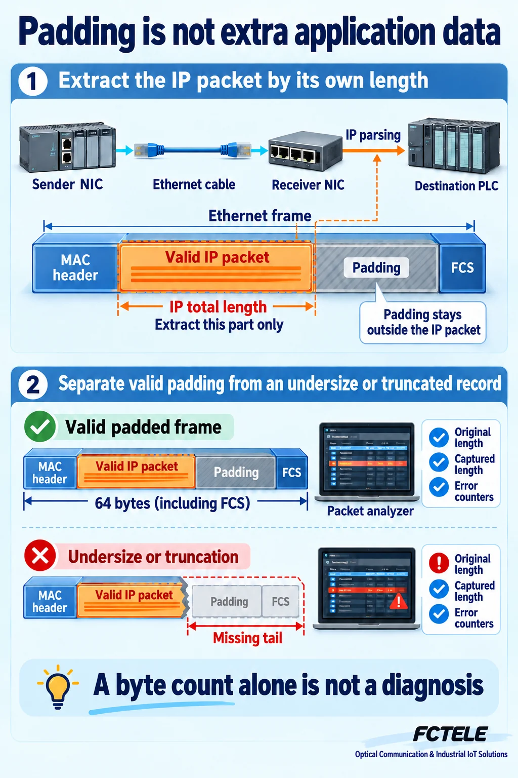
Apply the distinction to an industrial switch connection
The published FCTEL mini DIN-rail five-port Fast Ethernet switch page lists five Ethernet electrical ports and 10/100M adaptation. This provides a real product basis for a PLC and HMI connection scenario. It does not establish capture facilities, port mirroring, special padding control or particular error thresholds. Verify the selected configuration against its own documentation.
If one terminal repeatedly sends short status messages while another transfers a larger file, application byte counts alone do not describe port load. Each frame also consumes encapsulation and transmission opportunities, including the required spacing. Many small messages can use processing and link resources. Begin with frame rate, actual traffic and application cycle observations rather than requiring complex formulas.
If a transparently transported application appears to gain trailing bytes, first verify protocol boundaries and the parser. Compare what the source, any converter and the destination each observe. Do not automatically treat Ethernet padding as part of a serial message, or change equipment modes simply to eliminate padding. Establish the affected layer first.
Use three questions to narrow a field investigation
First, identify the observation point: before source transmission, after peer reception or a copy supplied by a switch. Second, document the length convention: included headers, FCS availability and whether a complete frame was retained. Third, correlate protocol lengths, payload and error counters for the same application traffic. A single screenshot showing 60 bytes is insufficient.
For comparison, use a known short message in an isolated test environment or approved maintenance window. Preserve original captures and acquisition parameters from both ends. Confirm that the application extracts only its valid content and ordinary communications continue. Such a test validates that configuration and path; one tool display does not define every interface and switch.
Finally, observe whether the anomaly follows a port, cable or capture method. Retain raw evidence instead of only annotated screenshots. The principle is simple: the outer frame has a minimum format, the inner application has its own length boundary, and capture software records one stage of processing. Keeping those three separate helps locate a real fault.
Sources and product evidence
Wireshark: Ethernet; IETF RFC 894, April 1984; Cisco padding troubleshooting document, updated July 16, 2021. General mechanisms do not transfer platform-specific commands or defect conclusions to other equipment. Product evidence: FCTEL mini DIN-rail five-port Fast Ethernet switch, Chinese-language page. Verify the selected version. Illustrations are generic concepts made with AI assistance.
Translated from the Chinese technical article: Read the original Chinese article.
Common practical questions
Is a 60-byte capture an invalid short frame?
Not necessarily. A common capture omits the four-byte FCS. Verify the observation point, original length and captured length.
Does padding become a new PLC command?
It should not. A parser must use the upper-layer protocol length rather than treating outer padding as extra application data.
Does every short message need 18 padding bytes?
No. Eighteen bytes applies only to the untagged example in this article; the original content and encapsulation determine the actual padding.
Scope and further reading
Generic Ethernet padding and capture concepts, not measurements or guaranteed model-specific behavior.
Related CRC and FCS guide · Related preamble and frame-gap guide
