


FCTEL Original Technical Article · FCTEL Technical Team
First published: 2026-10-07 · Last modified: 2026-10-07
An industrial switch can show an active link while a PLC intermittently times out. That does not immediately establish a performance problem. A cable, termination or transceiver circuit can alter received bits, while congestion can discard an otherwise intact frame. CRC is the calculation method; FCS is the Ethernet field that carries its result. Understanding their position in the receive path makes error counters meaningful and prevents every incident from being reduced to the same vague explanation of packet loss. This article describes general mechanisms. Illustrative data is not FCTEL test data.
Open the original image for detail. Scroll horizontally to read the diagram labels at full size.
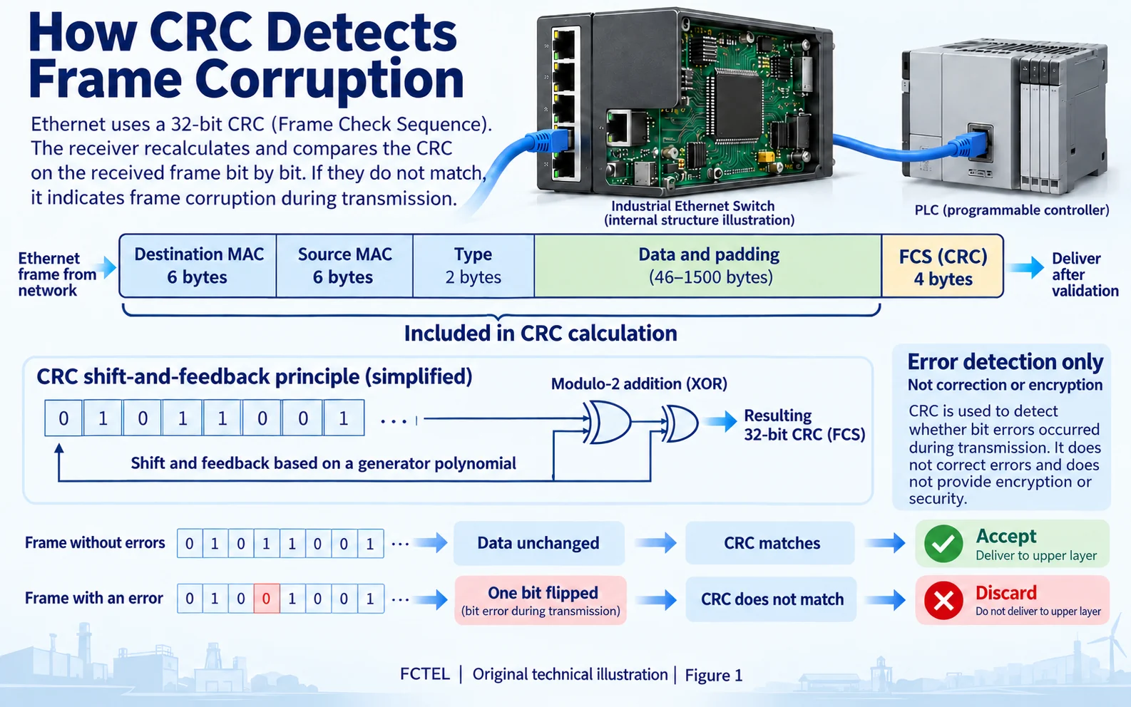
Why an Ethernet frame carries an FCS at its end
The transmitting MAC assembles the destination address, source address, type or length, data and any required padding, then appends a four-byte FCS. An 802.1Q tag, when present, is also included in the protected frame content. The preamble and start-of-frame delimiter support synchronization but are outside this CRC coverage. The interframe gap is not protected data either. Drawing the FCS at the frame tail makes an essential timing constraint visible: the receiver must see the check field before it can finish checking this frame.
Copper carries electrical signals and fiber carries optical signals. The PHY recovers bits from those signals. Attenuation, reflection, crosstalk or a transceiver fault can cause a transmitted zero to be interpreted as a one. Link UP confirms that a physical connection has been established; it does not certify every frame. The receiving MAC recomputes and checks the integrity relationship. A failed check makes the frame unsuitable for reliable delivery.
Distinguish the FCS from higher-layer checks. It protects the current Ethernet frame and does not replace TCP, UDP or application integrity mechanisms. When a switch changes protected content such as a VLAN tag, the outgoing FCS must match the outgoing content. A successful check at one receive port therefore does not certify the entire application-data path, or prove that the sender originally generated the correct information.
CRC uses shifts and XOR, not ordinary addition
A useful model treats a bit sequence as a binary polynomial and applies modulo-2 arithmetic with a specified generator polynomial. Addition and subtraction become XOR, without ordinary arithmetic carries. Hardware often implements this using a shift register and feedback XOR network, updating its state while bits arrive rather than asking software to process every byte. Ethernet uses a 32-bit CRC. The transmitter and receiver must agree on the polynomial, initial state, bit order and final processing rules; an arbitrary implementation named CRC32 is not automatically compatible.
For teaching, it is convenient to show the transmitter generating an FCS and the receiver recomputing the result over the received content and comparing it. A real circuit can instead process the frame including its FCS and test for the specified fixed residue. Both approaches validate the same relationship. CRC detects many classes of bit errors, but it does not identify the bit that needs correcting or guarantee detection of every possible error pattern. It contains no secret key and cannot replace encryption, authentication or a tamper-resistant signature.
Open the original image for detail. Scroll horizontally to read the diagram labels at full size.
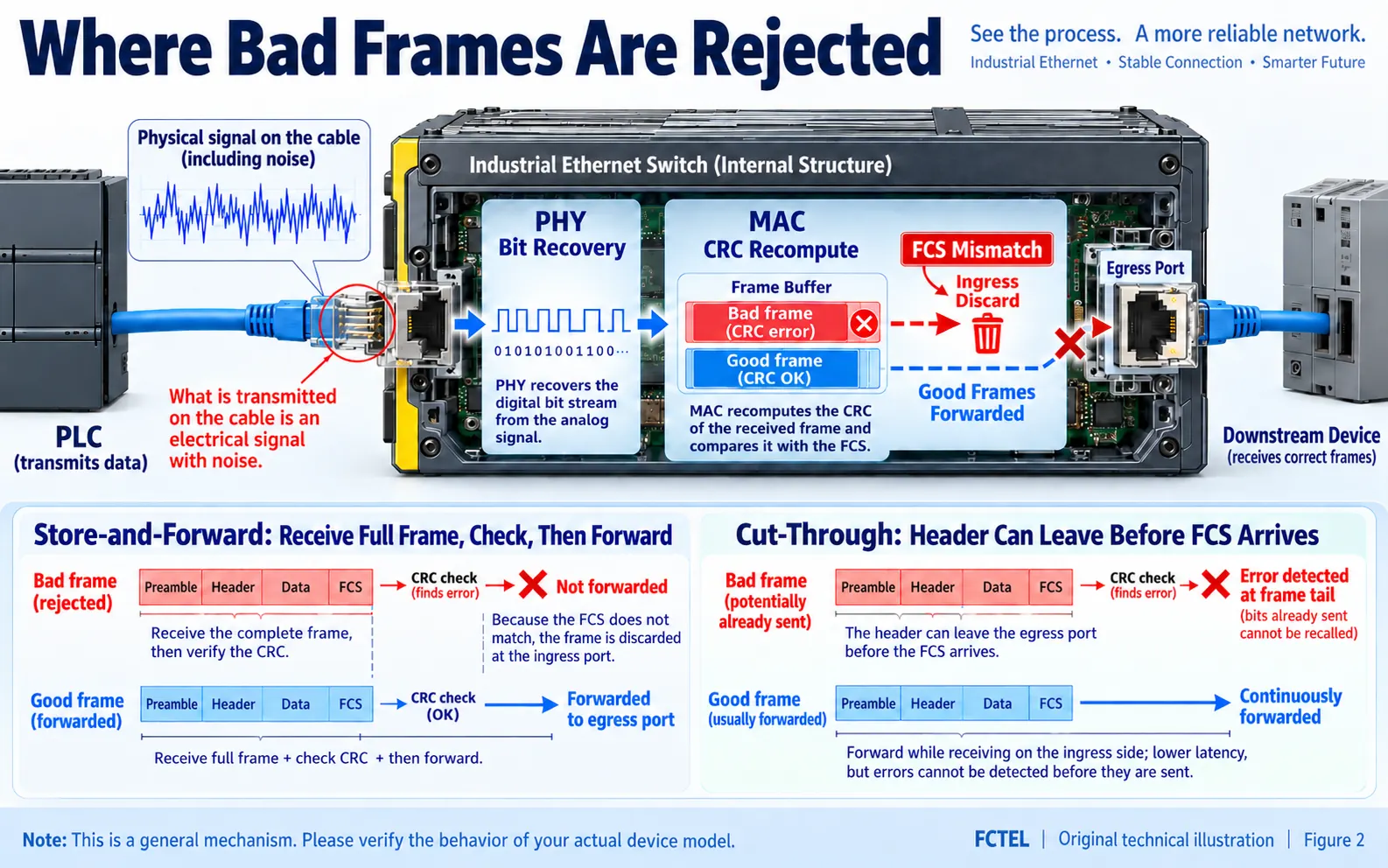
Why an ordinary packet capture may never show the bad frame
A typical receive path runs through the interface, PHY, MAC integrity check, switching or receive buffer and higher-layer processing. When a MAC or NIC rejects a bad frame before handing it to a driver, an ordinary capture program sees only the surviving traffic. An absence of CRC errors in a capture therefore does not clear the electrical link. Many NICs also remove the FCS, so the captured length and the on-wire frame are not identical. Keep switch ingress counters, endpoint NIC statistics and capture records together.
Store-and-forward operation receives the complete frame before checking it and making a forwarding decision; a failed check normally causes ingress rejection. Cut-through operation may start transmitting the header before the tail arrives, so corruption can reach subsequent links. Handling and counter behavior depend on the chipset and firmware. Do not infer the forwarding mode merely from the phrase industrial switch, or assume errors on several devices prove several independent failures. Confirm the forwarding behavior and counter meanings for the actual FCTEL model.
Open the original image for detail. Scroll horizontally to read the diagram labels at full size.
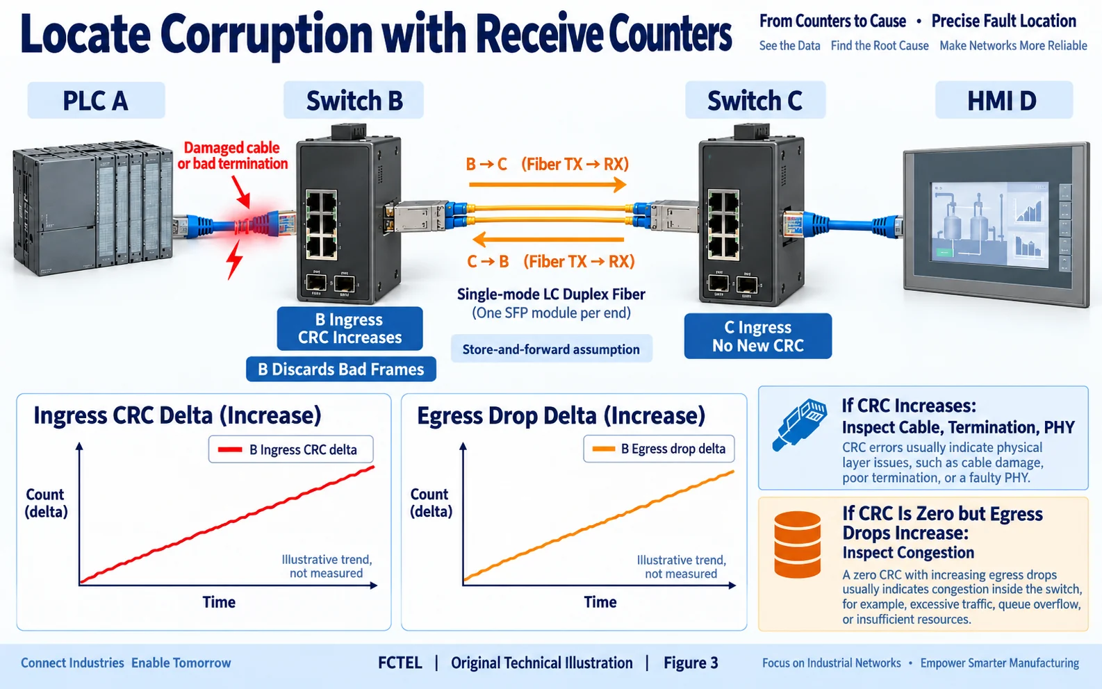
The receiving counter points to a link segment, not a guilty device
If PLC A transmits toward switch B and B's ingress CRC counter continually increases, first examine the A-to-B segment: A's transmitter, patch cable, wiring connections and B's receiver circuitry. B reports a failed integrity check; that counter alone cannot assign blame to A. Traffic in the reverse direction follows another receive path and may behave differently. A duplex fiber connection similarly requires separate examination of local TX to remote RX and remote TX to local RX.
Use deltas over the same observation window rather than lifetime totals. Save a baseline, wait a fixed interval, then compare the CRC increase, received-frame increase and application timeouts. A teaching example of ten newly errored frames is not a product specification. Input errors can include CRC, length and other causes; discards can include policy or resource decisions. Counters are not necessarily independent, so adding them indiscriminately does not yield a valid overall loss rate.
After a counter reset, preserve the time and action record so that deltas from different ports refer to the same observation window.
Test corruption and congestion as separate hypotheses
An intact frame can still be discarded when several inputs converge on a slower output and the queue has no space left. No bit error is required. Output-drop or buffer-related counters may rise while CRC remains unchanged. Conversely, CRC growth under light load strengthens the case for examining cables, contacts, interfaces and interference. Zero CRC does not prove the entire network is healthy: errors may occur on another port, or the device may not expose the relevant statistics.
Start with a known-good patch cable. Change only one component at a time and keep traffic and observation periods reasonably comparable. For copper, inspect pair termination, contact quality and separation from power wiring. For fiber, check clean end faces, TX/RX direction, module compatibility and power against the actual specification. DDM power is supporting evidence, not a substitute for frame integrity checks; a single reading does not prove a failed module. When needed, schedule a maintenance window and compare controlled traffic in both directions.
A timeout can also originate in a blocked application task, a device restart or an incorrect configuration. Preserve the symptom, then establish the observation layer: is the link established, is the frame intact, does the queue accept it, and does the application respond on time? If only application logs are available, leave the cause unconfirmed rather than substituting a switch replacement for diagnosis.
Keep an acceptance record that another engineer can reproduce
FCTEL's published managed switch with 24 Gigabit electrical ports and four Gigabit SFP optical/electrical options is a relevant entry point for industrial copper and fiber connectivity documentation. This article does not promise an unpublished CRC command or chipset architecture for that product. Confirm which ingress, egress and optical metrics the installed firmware exposes, including reset, wraparound and clearing behavior. Do not erase production counters for convenience without first preserving the baseline.
An acceptance record should include the topology, port numbers, media and modules, observation interval, load conditions, before-and-after counters, each replacement action and application recovery. Stopped bad-frame growth is evidence of improved transmission, but timeouts, latency and continuity also need checking. State that no new errors appeared under the tested conditions, rather than promising that packets will never be lost. Separating the mechanism, observation and conclusion makes the investigation reproducible.
Technical references: Cisco documentation on CRC/FCS mechanisms. Related FCTEL resources: Technical Articles and industrial switch product documentation (Chinese).
