


Why four zeros can contain pulses
Alternate
Ordinary marks alternate in polarity.
Substitute
The count of ordinary marks since the last V selects a pattern.
Decode
A valid substitution returns four zero bits.
Bench verification checklist
Use a known bit pattern and record line code errors separately from payload bit errors.
Look at an optical terminal’s E1 electrical port on a bench. The input is a stream of binary bits, but an oscilloscope may show positive pulses, negative pulses and empty intervals. A pulse can even appear where the input contains four consecutive zeros. Why does the receiver not interpret it as a data one? Both ends follow a substitution rule. To decode the line, the receiver considers the polarity and context of the pulses.
Start at the electrical port
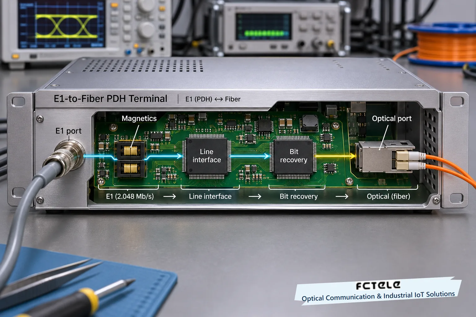
Feichang’s plug-in PDH optical terminal with 16 E1 and four Fast Ethernet interfaces lists HDB3 for its E1 ports, with 75-ohm unbalanced and 120-ohm balanced interfaces. This guide concerns the coding at the copper E1 interface. After receiving an electrical E1 signal, the terminal can recover timing and bits and then multiplex them onto its optical link. The optical equipment determines that link’s format. The HDB3 label on the electrical port does not imply that the fiber carries corresponding positive and negative voltage pulses.
E1 has a nominal bit rate of 2.048 Mbit/s, so each bit slot is about 488 ns long. For each slot, the transmitter must decide whether to send a positive pulse, a negative pulse or no pulse. The receiver must distinguish those states and sample at the right time. The nominal rate tells it the approximate slot duration. In operation, the receive circuit tracks timing from changes on the line so that the sampling point does not drift away from the intended decision point.
For a conceptual diagram, reduce the waveform to positive, zero and negative symbols. A real E1 pulse has specified shape, amplitude and width. It does not necessarily fill its entire bit slot. The diagrams locate each pulse in its slot. For electrical acceptance testing, use the proper interface, test point and pulse mask instead of comparing the trace with a conceptual staircase.
Why alternating polarity alone falls short
Start with Alternate Mark Inversion, or AMI. A one produces a pulse and a zero leaves its slot empty. Each ordinary one reverses the previous nonzero polarity. If the previous one was positive, the next is negative, however many zeros separate them. Alternation reduces the tendency toward a sustained polarity imbalance. It also gives the receiver another clue: two consecutive nonzero pulses of the same sign warrant checking against the coding rules.
A long run of zeros gives AMI no new transitions for timing. If the data contains many consecutive zeros, the transmitter keeps advancing its bit clock while the line remains without pulses. The receiver cannot easily find each slot boundary from that interval alone. HDB3 replaces every group of four consecutive zeros with a prescribed pattern containing pulses. The replacement still occupies four slots, so the line bit rate is unchanged and no position is inserted into the payload.
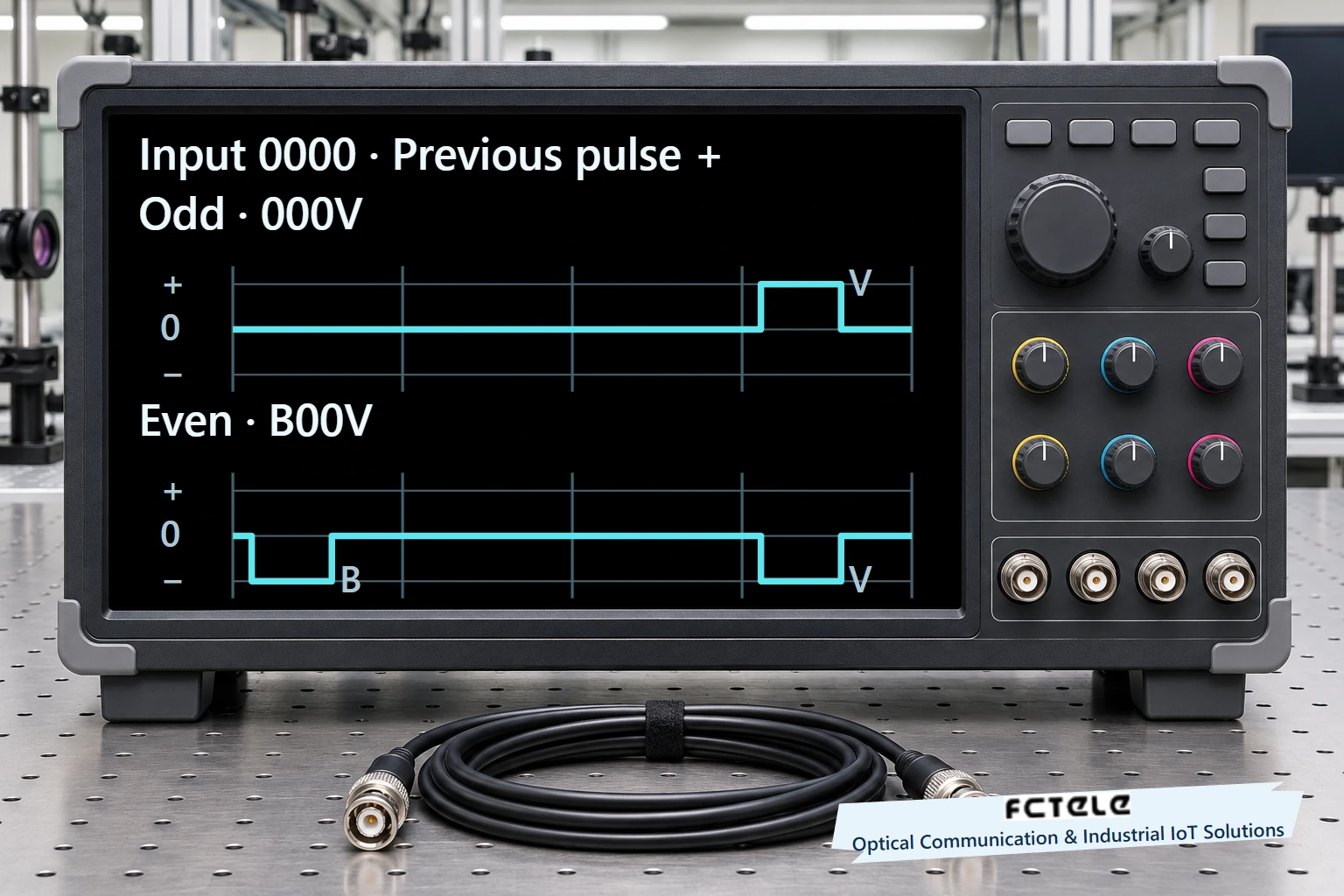
V is the violation pulse. It repeats the polarity of the preceding nonzero pulse and thus breaks the ordinary alternation rule. B is a balancing pulse that obeys normal polarity alternation. On encountering V, the receiver checks the preceding slots to determine whether the substitution is 000V or B00V. A same-sign pulse by itself does not prove that the transmitter deliberately encoded a run of zeros.
Work through both four-zero substitutions
The transmitter counts ordinary nonzero data pulses since the last V. If the count is odd, it uses 000V. With a previous positive nonzero pulse, the four slots are zero, zero, zero and positive. The last pulse repeats the previous positive sign and is therefore V. For example, if the last V was negative and just one ordinary positive pulse followed it, this positive V keeps the two violations opposite in polarity.
If the count is even, the transmitter uses B00V. Suppose the previous V was positive and no ordinary pulse has followed it when the next four zeros arrive. Zero is even. The transmitter starts the group with a negative B, alternating from the preceding positive pulse, leaves two empty slots and finishes with a negative V. The resulting group is negative, zero, zero, negative. The final negative repeats B and is a violation. This V is negative while the preceding V was positive.
The count concerns ordinary pulses since the last violation. It is not the total number of pulses ever sent. Knowing only that the preceding nonzero pulse was positive is also insufficient. The last pulse can be positive in both examples above, yet the different parity history yields different four-slot patterns. The encoder needs both polarity and state since the previous substitution.
Recover the bits and test the right layer
The receiver first decides at the appropriate sampling time whether each slot contains a positive pulse, a negative pulse or no pulse. It then checks the pulse relationships using HDB3 rules. Ordinary alternating data pulses correspond to ones. When it encounters a violation, the decoder considers the relevant four slots. For a valid substitution, it restores all four zeros, including the position occupied by B if present. The oscilloscope can therefore show pulses while a bit-error tester decodes all zeros. A decoder needs enough context for this decision. The hardware implementation determines how it stores that context and the processing delay.
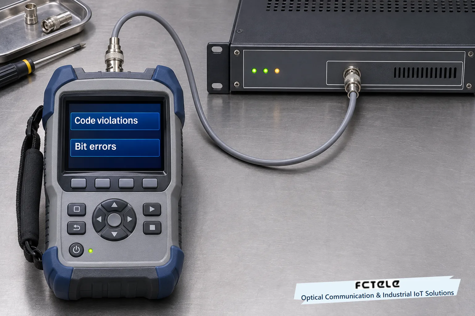
A missed pulse, or a reflection or noise event mistaken for a pulse, can disturb this context. Separate line-code violations from payload bit errors. The former concern whether the received line follows the code. The latter require comparing decoded data with a known test pattern. A valid intentional V is part of HDB3, so a line-error measurement should not treat every valid substitution as a fault. Consult the equipment and instrument definitions for exactly what their counters measure.
On the bench, use a matching E1 tester and a short cable to establish a baseline in one direction. Substitute the actual line during an approved maintenance window. With a known pattern, record line errors, bit errors, synchronization and measurement times together. If the short lead works and errors rise with the actual line, check termination, connectors and attenuation. If line results are clean while service fails, check framing, timeslot mapping and end-to-end data. Each measurement belongs to an identifiable layer. A synchronization light or a waveform alone cannot certify service.
Document where each measurement came from
Two observations are easy to mix up. First, zero on the line means that the slot contains no pulse. The instrument baseline may vary with coupling, noise and probe position, so the exact appearance of zero voltage on screen is not the criterion. Second, recovered line timing provides a sampling reference. It does not establish that the E1 frame was found correctly or that telephone signaling or data assignment works. Record whether each measurement came from the electrical port, the decoder output or the service endpoint so another engineer can reproduce it.
For an offline exercise, write down the preceding state and input sequence. Specify the polarity of the last V, list any ordinary pulses after it and then mark the four zeros. A trace that starts in the middle of the sequence omits the history that determines parity. Four visible slots alone cannot establish which branch the encoder took. Keeping the full pattern also lets you check that consecutive V pulses alternate and that the decoder returns four zeros in the original four positions.
Sources and scope
ITU-T G.703 Annex A · Feichang 16E1 plug-in PDH terminal specifications (Chinese)
Translated from the Chinese technical article: Read the original Chinese article.
Common questions
Why do four zeros produce pulses on the line?
HDB3 substitutes 000V or B00V within the same four slots to maintain transitions for timing recovery.
How does HDB3 choose between 000V and B00V?
Use 000V for an odd count of ordinary pulses since the last violation and B00V for an even count.
Does a V pulse always indicate a fault?
A valid HDB3 substitution deliberately uses V. The decoder checks polarity and neighboring slots before restoring the original zeros.
Further reading
Why Classical CAN inserts stuff bits · What a gigabit fiber port sends between frames
