

Why does the fiber stay active without traffic?
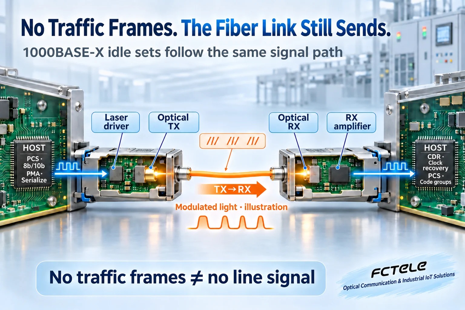
An established 1000BASE-X link sends idle ordered sets between frames. These patterns help maintain clock recovery and code-group alignment.
Serialize
The PCS encodes bytes before the module converts the serial signal to light.
Align
Recognize a comma, then validate subsequent groups to establish synchronization.
Observe
The PCS carries idle sets while an ordinary capture reports only delivered frames.
Functional illustrations, not a product circuit or measured trace.
01 · Match the PHY
Confirm 1000BASE-X mode and compatible optics.
02 · Separate evidence
Keep optical power, coding status and frame counters distinct.
03 · Reproduce the test
Use numbered frames and compare the same time window.
Bench verification checklist
- Record both port modes and module identifiers.
- Record baseline power and available error counters.
- Send numbered test frames and compare counter deltas.
- Use PCS diagnostics to identify ordered sets directly.
Two industrial switches remain linked over gigabit fiber after you disconnect the devices that generate traffic. A packet capture can show no frames even though the fiber is still carrying a signal. On an established 1000BASE-X link, the transmitter sends defined idle ordered sets between frames. The incoming signal gives the far end a clock to recover and recognizable patterns to align its code groups. The receiver can then read the next frame as it arrives.
Follow the signal through three interfaces
FCTEL’s DIN-rail managed industrial switch provides an example of a gigabit SFP uplink. Its product specifications list 1000BASE-SX and 1000BASE-LX media. This guide covers the normal data-transfer state of that class of 1000BASE-X interface. SFP describes a module form factor. Check the operating mode and compatible modules at both ends before replacing one.
To transmit a frame, the MAC supplies frame bytes to the physical coding sublayer, or PCS. The PCS represents data and control information as code groups suitable for the serial link. The module converts the electrical serial signal to light. The far end converts it back to electrical form, recovers the sampling clock, aligns and decodes the code groups, and hands the received frame to its MAC. The diagram separates these functions for clarity. Real hardware may integrate several of them in one chip.
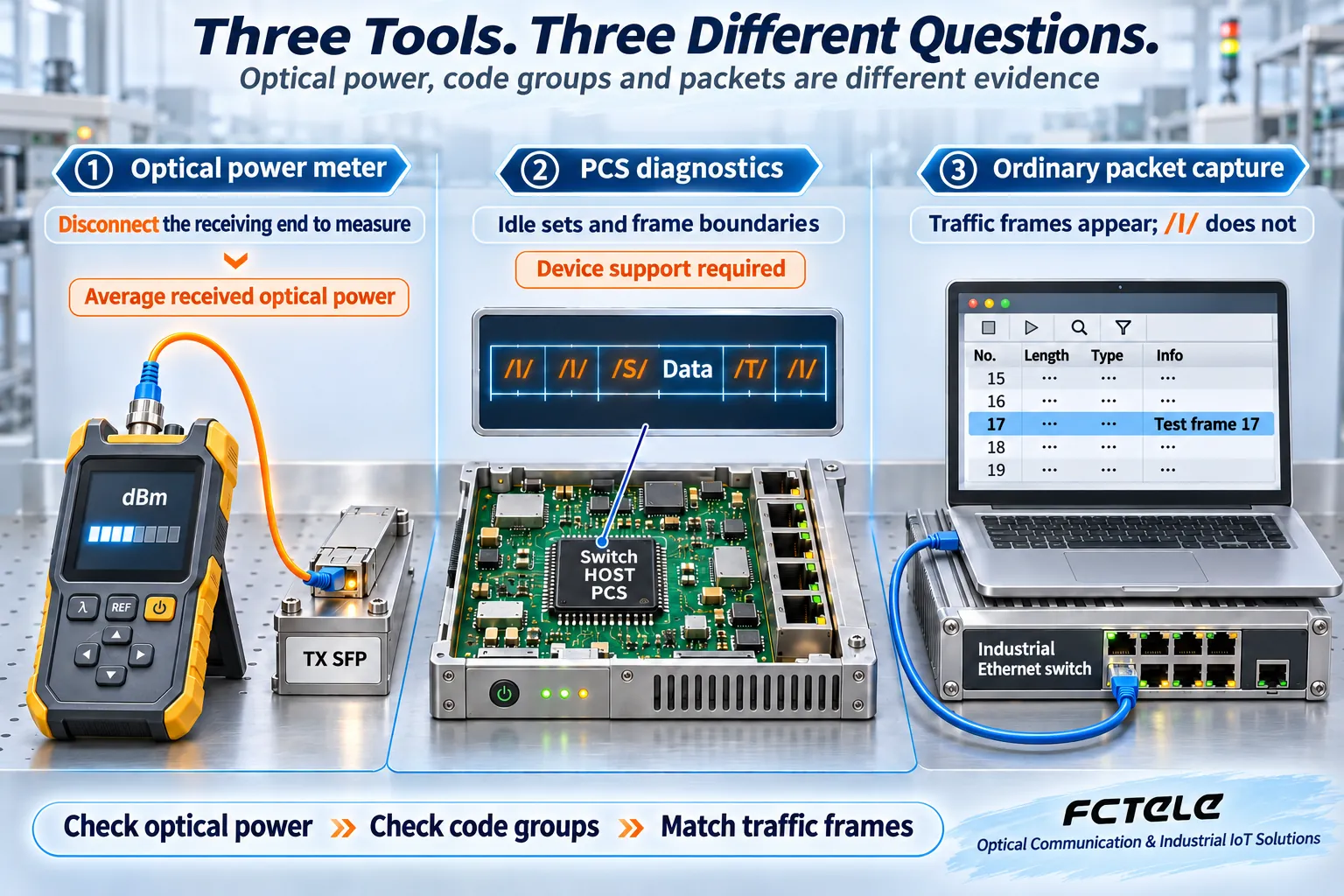
An optical power meter and a packet capture observe different points. The meter measures how much light arrives over a period of time. A conventional network adapter normally captures frames that have already made it through the receiver. Neither measurement shows whether the receiver correctly recognized the intermediate code groups. An empty capture is compatible with an active optical signal, and a power reading alone cannot confirm correct decoding.
Why one data byte takes ten line bits
8b/10b maps eight data bits to a ten-bit code group. The encoder selects a group from a defined mapping. It limits runs of identical bits so the receiver gets transitions it can use to recover the sampling clock. It also controls the long-term difference between ones and zeros, helping limit baseline wander in the receiving circuitry.
For every eight data bits, the serial link sends ten line bits. Ignoring framing and idle overhead, a data rate of 1 Gb/s therefore corresponds to a serial line rate of 1.25 Gb/s. Each binary line symbol carries one bit, so the symbol rate is also 1.25 GBd. Application throughput is lower than the MAC data rate once headers, interframe gaps and higher-layer protocol overhead are included.
The encoder tracks running disparity, which describes the accumulated bias between ones and zeros already sent. Some characters have positive and negative forms, and the current disparity determines the valid choice. Even balanced code groups must follow the encoding rules. A receiver can report an invalid code group or a disparity violation. Because interference may also turn a valid group into a different valid group, the frame check sequence, or FCS, still has a role in checking the received frame.
How the receiver recognizes idle and finds its boundary
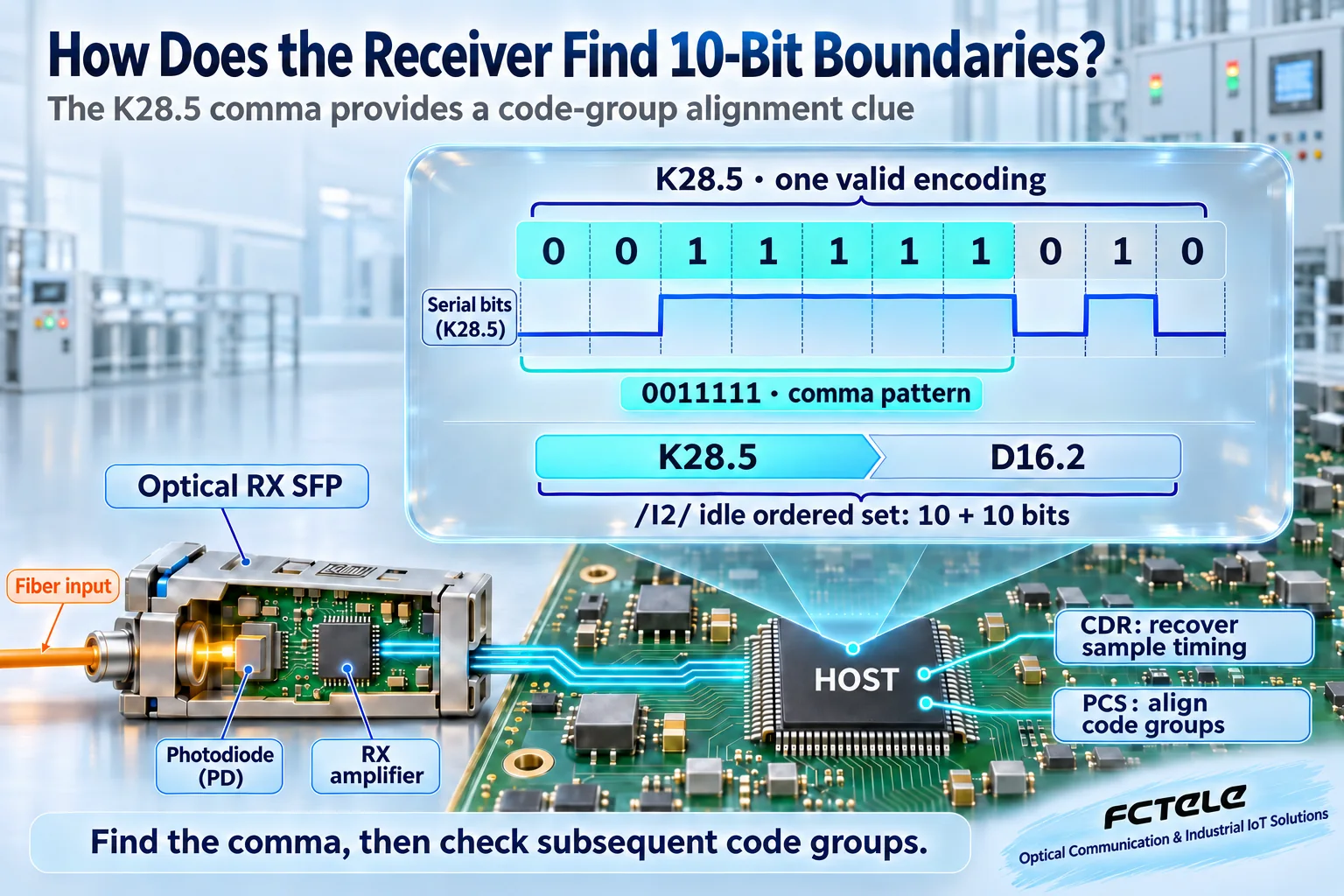
An all-zero stream would offer no transitions for the receiver to track. With only a raw stream of sampled bits, the receiver also needs a way to tell where each group of ten starts. The 1000BASE-X idle ordered set consists of two legal code groups. A common idle, /I2/, carries control character K28.5 followed by data character D16.2. /I1/ uses D5.6 after K28.5 and has a different effect on running disparity.
In one form of K28.5, 0011111010, the leading 0011111 is the comma pattern. It gives the receiver a recognizable alignment cue. The receiver also checks the following groups as part of synchronization. Clock recovery determines when to sample the signal. Comma alignment determines where to divide those samples into groups. A recovered clock can be stable while the group boundary is still wrong.
When the next frame arrives, the PCS marks its start with a control character. It marks the end with a terminate character and returns to the applicable idle sequence. Ordinary packet capture does not report these physical-layer control characters as Ethernet frames. This example describes established links. A link negotiating its configuration can send configuration ordered sets during a period with no application traffic.
Check the link at three observation points
Build an isolated bench setup with matching optical modules and confirmed port modes. Use a short patch lead to establish a stable link. Start without generating test traffic. Record the Link indication and received optical power. Use digital diagnostics if both the module and host support them, or a suitable optical meter following the site procedure. Frame counters do not count PCS idle sets as frames. The equipment may still generate management traffic of its own.
Next, send a small numbered burst from side A. Compare the changes in transmit and receive counters and match the sequence numbers in the capture at side B. If traffic counters stop increasing after the burst while the link stays up, that observation is consistent with the PCS sending idles. To identify the exact ordered set, use a bench instrument or PCS diagnostic with 1000BASE-X support. A conventional capture adapter cannot provide that observation.
If drops recur, record optical power, link changes and available error counters over the same interval. A power drop accompanied by loss of synchronization or repeated link changes points to checking connectors, fiber direction, modules and port speed. If power is steady while physical coding errors rise, check module type, link quality and port configuration. If the link and code counters are stable while frame errors or discards rise, distinguish receive errors from egress discards and check which ingress first records the error. Consult the device documentation for the meaning and coverage of each counter. A missing counter leaves an observation gap.
Make the bench record reproducible
For test frame 17 in the illustration, record the transmit time, transmit and receive sequence numbers, and both port states. Take a baseline before sending and compare counter deltas afterward so older errors are not included in this trial. If the application reports a send but the optical uplink transmit counter does not move as expected, check the test ingress and forwarding decision. If A’s uplink transmits the frame and B’s capture misses it, check B’s ingress counter separately from the capture. Capture filtering after the network adapter can also hide a frame.
When replacing modules, change one variable at a time. Keep the port mode and fiber in place, swap in a known compatible module, and repeat the same test. Change the next item only if needed. That preserves evidence of whether the difference followed the module pairing or the link conditions. Frame 17 and the timeline are illustrative examples, not measurements or performance claims for a specific product.
Keep the physical-layer scope clear
1000BASE-T uses a different physical-layer mechanism on copper. Modules of the same form factor and multirate ports can also operate in different modes. Received light, a panel Link indication, PCS synchronization and correct delivery of a business frame are separate pieces of evidence. Record them separately together with the module identifiers, port mode and test sequence. That makes it possible to tell which part of the link recovered after a module replacement or fiber change.
Sources and scope
AMD/Xilinx PG047 — 1000BASE-X (Appendix C) · IEEE 802.3 — K28.5 · FCTEL gigabit fiber switch specifications (Chinese)
Translated from the Chinese technical article: Read the original Chinese article.
Common questions
Does a gigabit fiber port go silent between frames?
An established 1000BASE-X link continues to send idle ordered sets.
What does the K28.5 comma do?
It gives the receiver a recognizable bit pattern for finding the code-group boundary.
Can a normal packet capture show idle code groups?
Typically no. Use an instrument or PCS diagnostic that supports 1000BASE-X.
Further reading
4B/5B coding on Fast Ethernet · Optical power and signal clarity
