


10BASE-T / LINE CODING
Where does the clock come from?
Manchester coding gives every transmitted bit a midpoint transition. A 10BASE-T receiver uses those transitions to track timing and recover the bit values. Boundary edges may also appear, so counting every edge gives the wrong result. The diagrams below explain the IEEE 802.3 polarity convention and conceptual timing, without representing measured electrical waveforms.
01 · Represent zero
A falling mid-bit edge represents zero under the IEEE 802.3 convention.
02 · Represent one
A rising mid-bit edge represents one. Both halves belong to the same data bit.
03 · Track the midpoint
Boundary edges can exist too. The receiver tracks bit timing rather than counting every edge.
Identify the mode
Read the negotiated port rate before comparing line codes.
Check 0011
Locate the four midpoints and distinguish them from boundaries.
Measure the right layer
Use a proper PHY fixture for waveforms and a capture for recovered frames.
Selection and verification checklist — expand
| Check | What to confirm | How to verify |
|---|---|---|
| Mode | 10BASE-T | Read both port states |
| Timing | 100 ns per bit | Check the documented instrument timebase |
| Result | Recovered frames | Compare counters and actual traffic |
An older controller sends data to an industrial switch over a 10 Mbps copper port without a separate clock wire. The switch still reconstructs individual bits from the electrical signal. The timing clues are in the signal transitions. In 10BASE-T Manchester coding, every bit has a transition at its midpoint. The receiver tracks that timing and uses the agreed transition direction to recover the data.
A data value and a line level are different things
Consider an unencoded representation that holds a high level for an entire one and a low level for an entire zero. This is called non-return-to-zero, or NRZ. Several identical bits produce a long unchanged level. A receiver must know how many bit periods that flat section contains. The oscillators at the two ends are not perfectly aligned at every instant, so agreeing a nominal rate does not remove the need for timing information.
Manchester coding represents each bit with two different half-bit levels. Under the IEEE 802.3 convention used here, zero is high then low, and one is low then high. This describes the polarity of the encoded differential signal. It does not permanently assign one cable conductor the role of a high-level wire. Actual amplitude, edge shape and polarity must be interpreted using the interface and measurement definitions.
There is still one data bit. Its representation on the line now has two half-bit intervals, so counting half-bits does not count payload bits. At the 10BASE-T data rate of ten million bits per second, a bit lasts 100 ns and a half-bit lasts 50 ns. These intervals help locate transitions in the illustration. They do not establish application throughput, which also depends on frame and protocol overhead.
Drawing 0011 reveals why boundaries can also change
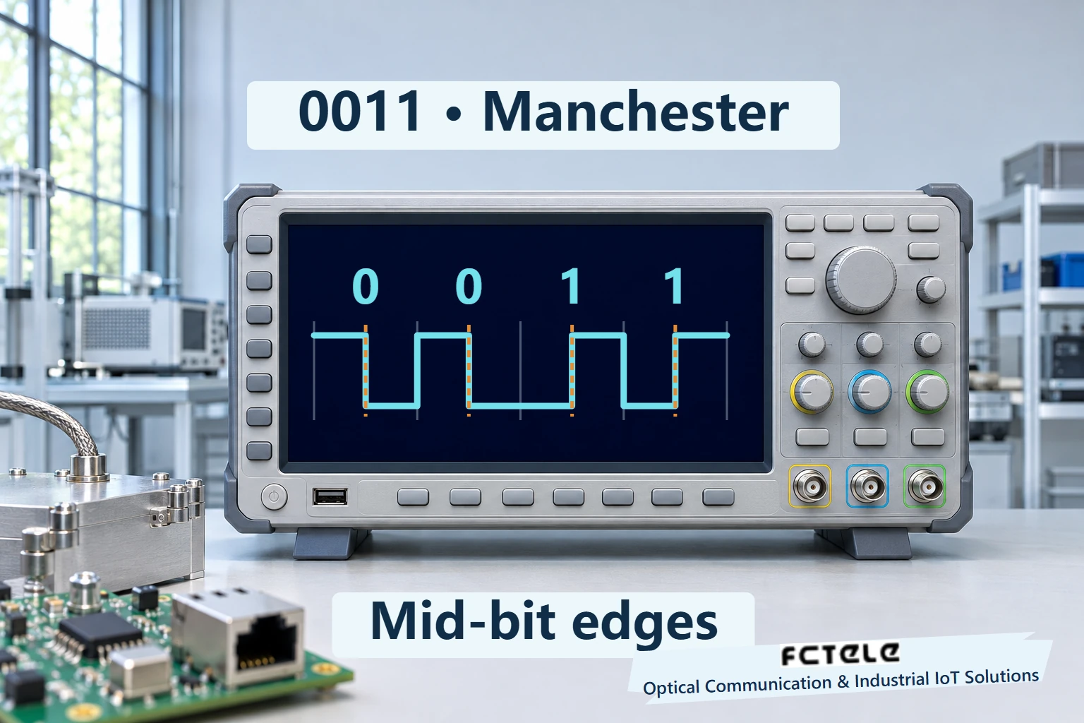
Expand the four-bit example 0011. The first zero is high-low, the second is high-low, and each following one is low-high. The eight half-bit levels are therefore high-low, high-low, low-high, low-high. The midpoint directions are falling, falling, rising and rising. Once bit boundaries are known, those directions identify the four values.
There can also be other transitions. The first zero ends low and the second starts high, producing a rising boundary edge. The second zero ends low and the first one also starts low, so that boundary does not change. Between two consecutive ones, the level returns from high to low. Midpoints always transition, while boundary transitions depend on the neighboring values. Treating every edge as a new bit midpoint would count the timing incorrectly.
The solid vertical markers in the illustration identify the four midpoints. Pale separators show bit boundaries. Read the bit width first, then inspect each midpoint direction. The ideal waveform illustrates the coding rule and omits transmit filtering, cable loss and noise. It does not establish the electrical compliance of a particular network interface.
Place the four-bit example on a time axis starting at an assumed zero. Its midpoints are 50, 150, 250 and 350 ns. The internal boundaries are 100, 200 and 300 ns. For 0011, boundary transitions occur at 100 and 300 ns but not at 200 ns. Counting these separately from the four midpoints shows why counting every edge fails. The zero is a drawing reference and does not imply that a receiver already knows the phase of an arbitrary signal fragment.
How the receiver tracks the timing
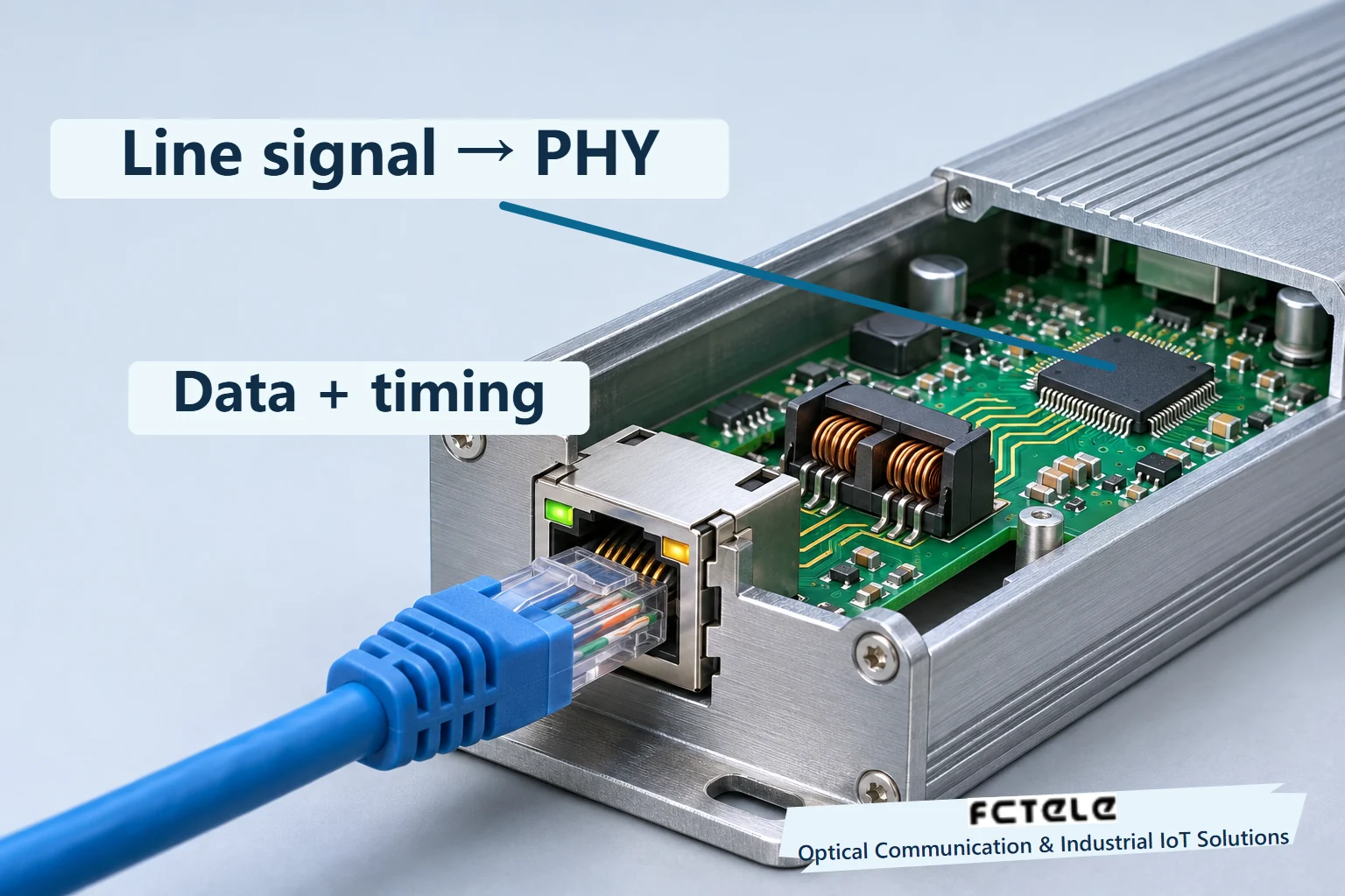
The connector and magnetics couple the twisted-pair signal into the physical-layer transceiver, or PHY. Its receive circuitry processes the analog signal into changes that can be detected. Clock recovery and decoding then track transition timing. The preamble supplies timing information at the start, while the mandatory midpoint transitions help maintain timing during reception. The recovered timing is an internal function. No additional clock cable runs beside the Ethernet cable.
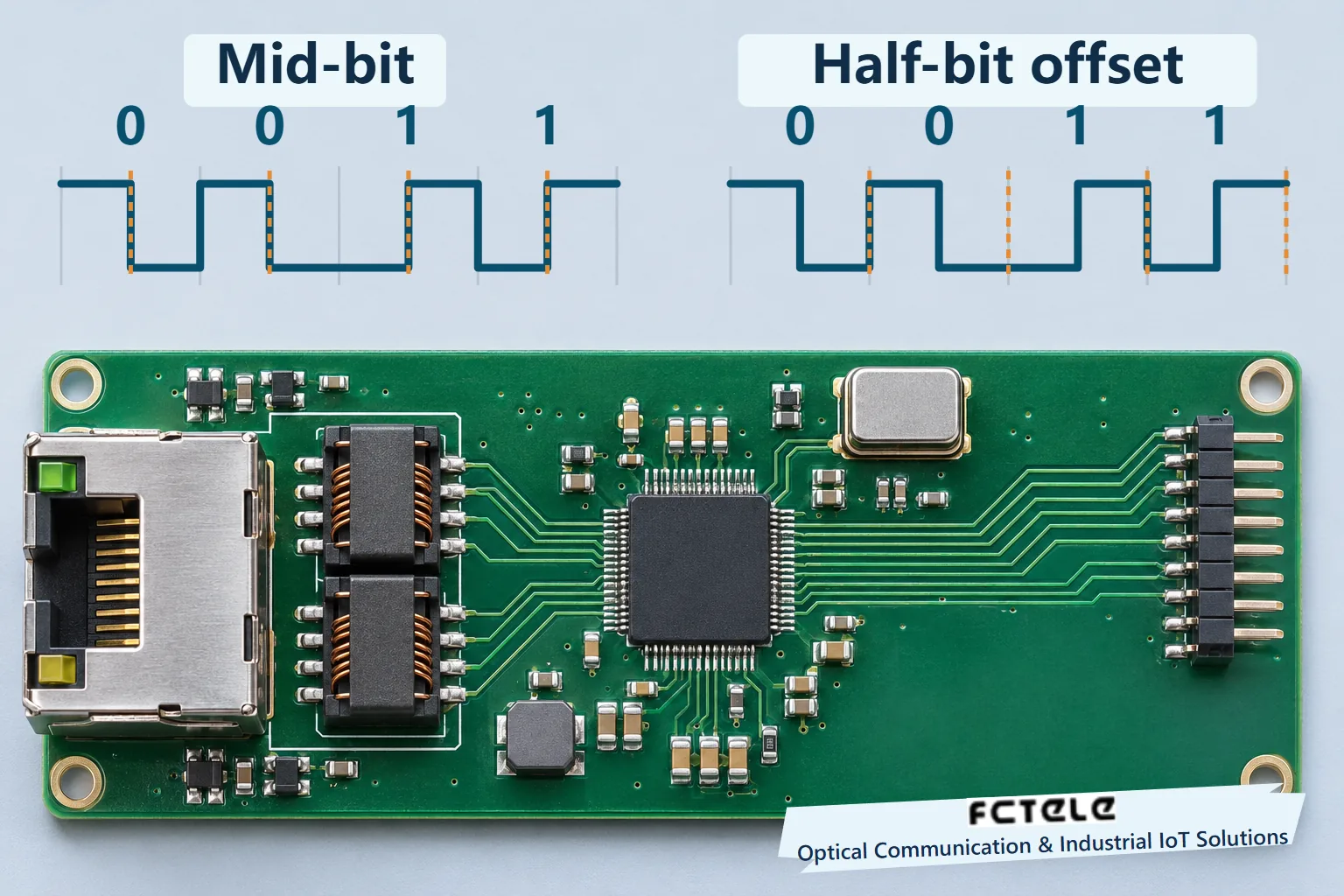
Think of the internal timing as a ruler whose position can be adjusted. The grid spacing represents the expected bit period, and its centers align with the intended midpoint transitions. It cannot simply shift half a bit whenever any edge appears, because a boundary edge could then move it to the wrong position. The actual receiver interprets transitions according to the code and its synchronization state, tracking phase changes within its operating limits. This analogy does not specify a complete phase-locked loop or a particular chip implementation.
The timing illustration places one set of midpoint markers correctly over 0011 and another set half a bit away. The misplaced windows encounter boundary transitions that sometimes exist and sometimes do not. An edge alone is insufficient. The receiver uses timing, direction and receive state together. Reconstructing the line symbols also does not complete frame validation. Frame boundaries and frame checks remain separate responsibilities.
Observing a real link
First confirm that the port connected to the older controller is actually operating in 10BASE-T mode. A switch described as gigabit can support multiple rates, while its negotiated mode depends on both ends and their common capabilities. The coding used by 100BASE-TX and 1000BASE-T differs. The waveform here also does not apply to 10BASE-T1L simply because that single-pair interface has a 10 Mbps rate.
Observing line coding requires suitable Ethernet physical-layer probing, fixtures and instrument settings. A conventional grounded probe attached to an unknown conductor can alter the measurement conditions. Follow the interface and instrument documentation on an authorized bench. Record location, polarity, rate, trigger and timebase. Establish whether the observed interval contains transmitted frame data or link-detection activity before interpreting transitions as payload.
A normal computer capture contains frames already recovered by the PHY and subsequent logic. A captured 0x00 does not correspond to a continuously low electrical line. Identical bits still transition under the line code. Receive errors are diagnostic clues, but do not identify clock recovery, cable, connector or another circuit as the cause on their own. Compare counters at both ends, a known-good short lead and appropriate physical-layer observations to narrow the fault.
Applying the mechanism to products and acceptance
Feichang’s steel-housed five-port gigabit DIN-rail switch lists 10/100/1000BASE-T interfaces. It is a real example of an industrial multi-rate copper interface. Verify the delivered model, version and negotiation configuration. This article explains the generic 10BASE-T mechanism without identifying the product’s PHY chip, exposing an internal test point or representing a specific enclosure’s actual circuitry.
Begin a reproducible verification with a short link. Record both models and operating modes, send identifiable traffic and compare receive statistics with application results. If waveform observation is needed, use the same fixture and timebase for the known-good and suspect conditions. Checking the half-bit sequence of 0011 explains the timing mechanism. Linking real measurements to the operating results is what supports an assessment of the installed connection. Longer stability checks still need the specified conditions and observation duration.
Sources and scope
TI DP83848-EP 10BASE-T transmitter and receiver · Microchip IEEE 802.3 Manchester convention · Feichang five-port industrial switch (Chinese)
Translated from the Chinese technical article: Read the original Chinese article.
Common questions
Does a zero stay low for a full bit?
In the IEEE 802.3 Manchester convention, a zero changes from high to low at mid-bit.
Is every edge a bit midpoint?
No. Boundaries between identical neighboring bits can transition too. Timing and synchronization state distinguish them.
Can an ordinary packet capture show the waveform?
A packet capture contains recovered frames. Line coding requires appropriate physical-layer measurements.
Further reading
How gigabit copper cancels local echo · What a gigabit fiber port sends between frames
