


Two devices both labeled PDH or both with RJ45 do not guarantee interworking. For a PDH optical multiplexer, compatibility should be checked separately for the service electrical interface, framing and clocking, optical-side organization, and auxiliary interfaces; pure E1 transport cannot automatically translate Ethernet, telephone, or application protocols. The first step in selection is to confirm what signal the site actually outputs.
The same type of plug can serve different purposes
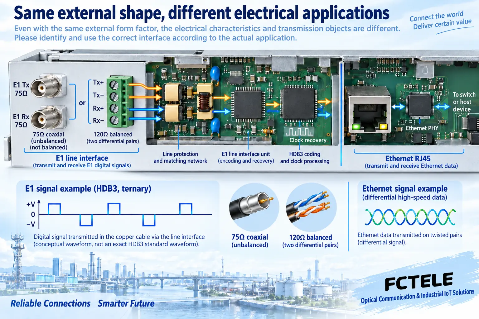
RJ45 is a connector shape and may be used for Ethernet, or it may be used by a device as a balanced E1 or management connection. The same port appearance only means the plug may fit; it does not prove that the pins, levels, line code, and processing method are the same. Coaxial interfaces such as BNC also cannot be judged by shape alone as E1, video, or another signal. Check the panel text, interface definition, and model documentation, then choose the corresponding cable.
Likewise, a Console or RS232 management port on a device is for configuration or status reading and is not necessarily a transparent user data channel. Treating a management serial port as a service port may both fail to transmit and affect operations and maintenance. A compatibility checklist should include purpose, not just write “one serial port, one network port”; for composite connectors, also obtain the pin definition and do not try plugging in based on a generic network cable wiring method.
E1 matching starts with electrical and timing conditions
The common nominal line rate for E1 is 2.048 megabits per second. G.703 specifies the relevant physical and electrical conditions, and common interfaces include 75-ohm unbalanced and 120-ohm balanced modes. The former usually uses separate coaxial paths for transmit and receive, while the latter uses corresponding balanced wire pairs. Connector conversion only changes the shape and does not necessarily complete impedance and electrical mode conversion; use suitable equipment or an explicitly supported interface configuration.
HDB3 is a common E1 line code that uses specified level changes to meet line transmission and clock recovery needs. It is not an IP protocol, nor a compression algorithm. Whether the line can receive also requires distinguishing whether framed mode, time slot arrangement, related checks, and signaling settings are used. Whether a transmission device that truly carries a whole transparent E1 and the service end perform framing termination are different boundaries; do not uniformly say that all devices parse all time slots.
“Plesiochronous” does not mean clocking needs no planning
The clocks of digital devices may have the same nominal rate but slight differences, and the system needs to coordinate these differences under permitted conditions. Transmission equipment recovers clocks from the input, performs tributary organization, and output processing, and the two service ends may also have their own synchronization requirements. Draw who provides the reference and who follows whom, then check the internal, line, or external clock selection. If both ends blindly follow each other without an effective reference, a single optical fiber cannot automatically solve it.
A brief light indication or a passing test may still be insufficient to find slips and intermittent errors. A slip involves buffering and data adjustment between different timing beats and is not the same as a physical fiber break. When replacing equipment, save the old clock mode and long-term error records, then test the new combination under the same conditions. Do not simultaneously change wiring, switch clocks, and change framing mode, otherwise it will be difficult to determine the cause after recovery.
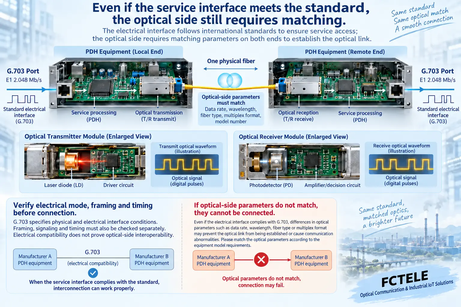
Why the optical ports may still not interoperate even when service standards match
The optical side of ordinary multi-channel E1 point-to-point PDH products may use the manufacturer’s own multiplexing, frame alignment, and control structure. Both devices meeting the G.703 E1 interface conditions does not prove that their optical-side formats are the same. A housing labeled “PDH” or also using 1310 nanometers is not enough to guarantee matching optical-side rate, channel organization, and remote management interaction.
Both ends must also confirm fiber type, single or dual fiber, wavelength pairing, transmit and receive directions, allowed receive power, and version compatibility. In dual-fiber, transmit connects to the opposite end’s receive; in single-fiber bidirectional, complementary wavelengths and correct pairing must be checked. A connector being able to guide light and digital data being able to be decoded are two different things. Before replacing across manufacturers or different series, obtain a clear interoperability statement and verify with actual equipment.
Ethernet capability should be judged by independent interfaces and operating mode
Feichang FCP-E4m provides one to four E1 channels, while FCP-E4F1m adds one 10/100 Mbps Ethernet interface; this is a specific model capability difference. Because both belong to PDH, one cannot assume both can be directly connected to a computer. When E1 and Ethernet share optical transmission, their capacity arrangement, forwarding method, and allowed service conditions in the device must also be confirmed; do not simply add the maximum numbers of different interfaces and call it the available throughput of all ports.
The FCP-E4F1m official website lists Ethernet loopback protection: when the optical line loops back, Ethernet data will not be looped back in the same way. This function is different processing from E1 remote interface loopback and can help reduce the risk of maintenance testing accidentally affecting the network, but it does not mean that any topology will not produce an Ethernet loop. VLAN transparent transmission or related support must also be checked according to the specific version; do not infer that it has routing, firewall, or VPN.
Protocol conversion requires corresponding functions, not guesswork
If one side has only E1 and the other side has only Ethernet, confirm whether an explicit Ethernet-to-E1 converter is needed and how the two sides are compatible. Some solutions may also involve E1 emulation or TDM over IP, that is, carrying traditional continuous services over a packet network according to rules. This is not the same mechanism as pure point-to-point PDH optical transmission; equipment, bandwidth, jitter, and clock requirements all need separate planning.
Analog telephone, video, or industrial bus also require suitable service interfaces. An ordinary E1 device is not a universal translator across international communication standards. Service organization names such as PCM-30 should not be written as “a network protocol automatically recognized by all PDH.” The correct approach is to list the source interface, bearer method, and receiving application separately; any missing conversion step must be completed by equipment with the corresponding capability.
How to turn compatibility into evidence when replacing old equipment
Assume the site already has four E1 channels and one end of the old equipment needs replacement. First photograph the models and versions at both ends, and record the ports used, impedance, line mode, clock, and optical interface. Have the supplier confirm whether the old and new combination is supported, then establish a short-link baseline. If only paired replacement is possible, clarify the maintenance scope; do not let purchasing staff choose another device with a similar appearance based only on port count.
During per-channel testing, give each channel an identifiable service or test sequence, check the numbering and direction, then record errors and continuous operating conditions. Finally restore the real application and check alarms. The compatibility conclusion should be written as “passed under these configurations and conditions,” not a general statement that all PDH and all protocols can interoperate. In this way, later expansion and replacement have a basis, and model options will not be mistaken for general functions of the entire technology category.
Sources: ITU-T G.703 digital interfaces;ITU-T G.704 frame structure;Feichang FCP-E4m;Feichang FCP-E4F1m. The principle illustrations are general principle diagrams, belonging to general mechanism illustration, not product photos, measured waveforms, or certification documents.
Related topics: PDH optical multiplexer and PCM sampling and quantization: at which layer analog voice becomes digital;How to upgrade an old PDH optical multiplexer network: retain E1, migrate SDH and packet transport;How to use PDH optical multiplexer RLB loopback: test path, errors, and service recovery;How to read parameters of an 8E1 PDH optical multiplexer: eight channels, impedance, and matching interfaces;How to select a PDH optical multiplexer: service capacity, optical budget, clock, and acceptance;How to troubleshoot common PDH optical multiplexer faults: continuous alarms, intermittent errors, and segmented testing
Translated from the Chinese technical article. Source first published: 2024-11-13. Source last revised: 2026-10-13T12:16:42+08:00. Read the Chinese source
