


RLB is often used to mean a remote loopback related status or control, but the abbreviation, loopback location, and operation method must be based on the specific model manual. Loopback sends test data back from a specified boundary to help judge that path; it cannot prove that all services are normal based on one lamp, and after it is enabled it may also affect the E1 that is currently running.
Why loopback helps with segmentation
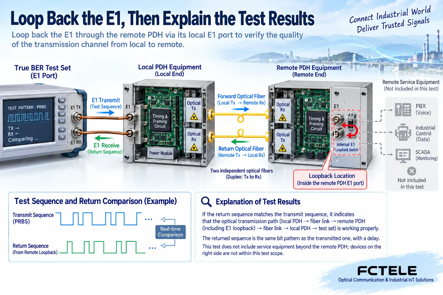
In normal communication, the signal from the test source or service source passes through the local interface, optical transmit, optical fiber, remote optical receive, and remote service interface, and is handed to the application for use. Loopback directs the signal to the return path at one of these boundaries, and the tester compares the sequence sent with the sequence received. In this way, bit errors can be observed around the included link segments, but the application after the return point does not take part in the same test.
It can be understood as sending a numbered test letter back to the sender from a certain station, and the sender uses it to check the part traveled there and back. This metaphor cannot be used to derive specific latency, clock mode, or all internal wiring of the equipment. Electronic loopback is usually controlled inside the equipment, while external shorting is another implementation; when the port definition is unknown, you should not wire it yourself to simulate a so-called universal loopback.
Near-end and far-end names are not enough to determine the scope
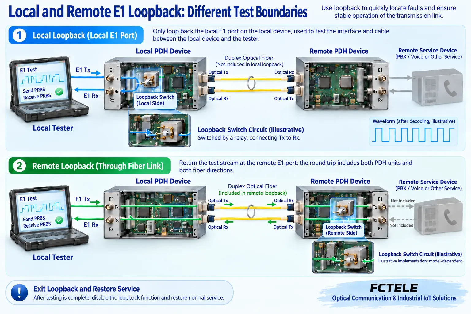
A local device interface loopback may cover only the local service line, or it may involve internal processing. A remote E1 interface loopback usually makes the test path pass through the transmission and optical path at both ends, but whether the return point is on the line side or the service side needs to be specified. There are also optical-side or different internal loopback locations, and they cannot all be drawn as the same arrow. The test record must state the location, direction, and channel, and cannot simply say “RLB enabled.”
The same product may support multiple modes. During loopback, whether the receive recovered clock or the internal clock is used, whether output to the outside continues, and the impact on other ports are all determined by the implementation. When there is no confirmation information for an unknown device, operation should be paused first and the manual obtained. Chip datasheets can help understand different return structures, but they do not prove that the complete unit definitely uses that chip or exposes the same menu.
Indicator lamps are not bit error testers
A loopback lamp may indicate that a request has been sent, that the far end has entered the mode, or merely that the local test switch is on. The specific definition depends on the model; a lit lamp does not automatically mean the returned data is exactly the same as the original data. A real bit error test requires a suitable test source, receive comparison, test sequence, rate and duration, and correct settings for frames and clock.
Bit error rate describes the proportion of errors among the tested bits, and indicators such as errored seconds describe the error situation within a certain observation time. These indicators have corresponding definitions, and a few minutes without seeing a red lamp cannot be treated as a formal report. Results under different test conditions should also not be compared directly. The test port, mode, time, and abnormal time points should be recorded so that the results can be linked to on-site service problems.
Increase the scope gradually from a short path
First use a known suitable tester and a short service line to verify the local interface and instrument settings, then move on to a test that includes the optical section and the remote boundary. Add only one segment at a time or change only one loopback point, so that changes in the results have locating value. If the local path passes but the remote path is abnormal, check the newly added optical transmission, remote processing, and related clock conditions, rather than directly concluding that the optical cable must be damaged.
If the remote loopback test passes but normal service still fails, the service equipment, wiring, time slots, and signaling after the return point may still not have been verified. Conversely, a test failure may also come from a test mode or clock configuration that is not suitable, and the complete unit cannot immediately be judged as faulty. Only by combining alarms, received power, port statistics, and actual wiring can the scope be narrowed. A single instrument result cannot be expanded into a guarantee that all channels are stable over the long term.
How Feichang remote loopback is used for maintenance
The Feichang FCP-E4m official website lists the command remote interface loopback function and provides related capability to observe remote status at the local end. It provides clues for maintenance between two locations, but the specific control entry, supported channels, and status meaning need to be confirmed according to the delivered version. This article does not invent button sequences and commands that the website overview does not provide; it also does not infer that all PDH units have a network management interface.
The FCP-E4F1m additionally introduces Ethernet loopback protection, avoiding sending Ethernet data back in the same way when a loopback occurs on the optical line. This shows that E1 testing and network port forwarding need to be distinguished; it does not mean that other models all have this function, and it cannot guarantee that any incorrect network wiring is safe. Before testing integrated service equipment, it is also necessary to confirm which interfaces will be affected, to prevent planning to test only E1 but accidentally interrupting other services.
How to test a single-channel intermittent abnormality
Assume that among four E1 channels only the second channel has occasional bit errors. First save the abnormal time and the alarms at both ends, then check the source, port, and clock of the second channel. Within the maintenance window, establish a local test for the second channel, then perform remote loopback according to the manual. If the problem appears only after the optical section is added, compare the receive conditions and the state of shared equipment; if only that channel is abnormal, also pay attention to that line’s interface and configuration.
The test sequence, time, and instrument settings should remain consistent, and other running channels must not be switched casually. If a certain segment test remains normal, what is recorded is that no problem was observed under the corresponding conditions, which is not equal to having ruled out all intermittent faults. Changes in service load, temperature, and power supply may trigger the problem only at specific moments, so follow-up should combine logs for continuous observation, rather than repeatedly enabling loopback to replace operations analysis.
Exiting the test is part of the complete procedure
Before operation, maintenance permission should be obtained, the original configuration saved, the affected scope announced, and the recovery method agreed. After the test ends, remove the specified loopback, confirm that the status at both ends has recovered, and recheck the port correspondence and actual services. If loopback is forgotten and not exited, the instrument may still show normal return, while the service signal is not delivered to the far end along the normal path.
The handover record should at least include the model, manual version, loopback location, channel, clock mode, test results, and exit time. The results should state the covered and uncovered scope. When an optical connection check is needed, use suitable tools and do not look directly into the optical output port; for electrical work and equipment disassembly and repair, handle it according to the corresponding qualifications and specifications. Reliable locating comes from a clear path and comparative evidence, not from an unverified expansion of an abbreviation.
Sources: ADI DS2155 interface and loopback materials;Feichang FCP-E4m;Feichang FCP-E4F1m. The principle illustrations are general principle diagrams and are general mechanism illustrations, not actual product photos, measured waveforms, or certification documents.
Related topics: PDH optical multiplexer and PCM sampling and quantization: at which layer analog voice becomes digital;How to judge interface compatibility of a PDH optical multiplexer: E1, Ethernet, and optical-side formats;How to upgrade an old PDH optical multiplexer network: keep E1, migrate to SDH and packet transport;How to read parameters of an 8E1 PDH optical multiplexer: eight services, impedance, and matching interfaces;How to select a PDH optical multiplexer: service capacity, optical budget, clock, and acceptance;How to troubleshoot common PDH optical multiplexer faults: continuous alarms, intermittent bit errors, and segmented testing
Translated from the Chinese technical article. Source first published: 2024-05-10. Source last revised: 2026-10-13T12:16:42+08:00. Read the Chinese source
