


A multimedia system can send sound over fiber using a dedicated audio optical transceiver, or using networked audio endpoints that support the corresponding protocol together with an Ethernet optical link. The two cannot replace each other just because both use fiber. At the same time, audio arriving successfully does not mean video and sound are already synchronized; conference echo, channel assignment, and processing delay still need separate design.
First answer: extend one audio line, or build an audio network?
Sending line audio from a classroom in a teaching building to a fixed control room is usually a clear end-to-end extension problem. An analog-input transmitter converts audio voltage into digital samples, encapsulates them, and then performs optical transmission; a matching receiver restores the samples and hands the analog audio to downstream equipment. Multiplexing arranges samples from different channels into a transmission sequence, and the receiver separates them again according to the same arrangement. Multiplexing must not be understood as mixing multiple audio channels into one program.
Networked audio, by contrast, organizes digital audio into network packets and establishes service routing between compatible endpoints. Switches handle Ethernet forwarding, and optical modules or fiber transceivers change the intermediate transmission medium; they are not responsible for automatically turning analog sound into Dante audio. The audio source and receiving device must have the corresponding protocol function, or a suitable audio network interface must be used, to form a complete system.
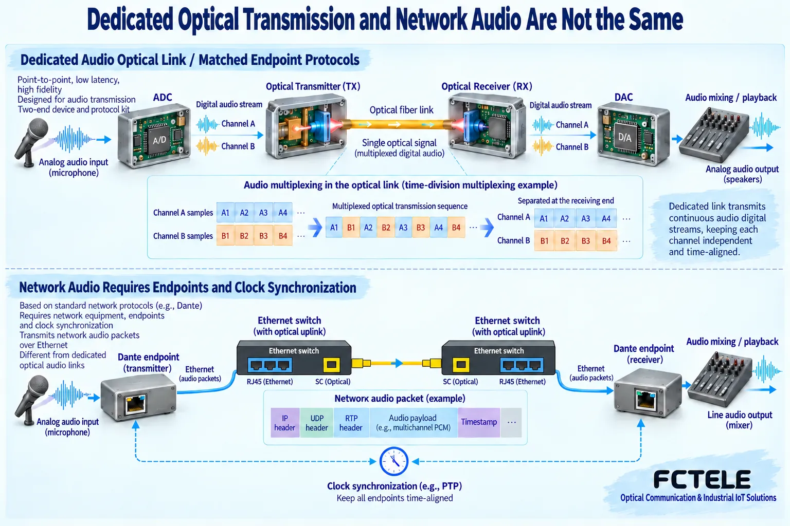
Dante official introduction It explains that Dante distributes digital media over standard Ethernet. What is cited here is the architectural concept; it does not mean that an ordinary audio optical transceiver supports Dante, nor that it will work normally when connected to any switched network. Names such as CobraNet, MADI, or AES/EBU correspond to different technologies and should not be listed as features common to all products.
Why channels, sampling, and clocks must match
The sampling rate is how many audio samples are read per second, and the bit width is the length of the numerical representation of each sample. As a calculation example, eight channels, each at 48,000 times per second, with 24 bits per sample, give a raw sample volume of about 9,216,000 bits per second, before packaging, line coding, and other overhead are counted. This example helps estimate traffic; it is not a parameter of any Feichang Technology model. The sampling rate is also not the upper limit of sound frequency, and even less is it the nominal rate of the optical port.
A digital receiver needs to consume samples at a suitable pace. If the clock that produces samples and the clock that plays them are not correctly coordinated, buffer abnormalities or sound interruptions may occur over long runs. Dedicated matching equipment can coordinate through its own line mechanism; networked audio must manage clocks, routing, and receive buffering according to the corresponding protocol. Two devices showing the same sampling rate does not mean the clock relationship is already correct.
Feichang Technology Digital audio product categories It lists products with different analog and digital interfaces. If an analog audio source already exists, a suitable analog input can be chosen; if digital audio already exists, the digital interface format should be checked. Whether video, data, or network channels are also needed depends on the specific model and ordering configuration; “multi-service” does not mean automatic conversion of any protocol. Level and power requirements for professional audio are described separately in Professional audio connection notes.
Why sound and picture drift apart
A camera output may go through encoding, transmission, decoding, and display processing; a microphone signal may go through sampling, audio transmission, digital-to-analog restoration, and power amplification. Even if the two systems travel along the same line, the time spent in processing stages may differ. Seeing the mouth move first and hearing the sound later, or hearing the sound before seeing the action, means the end-to-end arrival times are not aligned; it cannot be explained only by whether the optical port is connected normally.
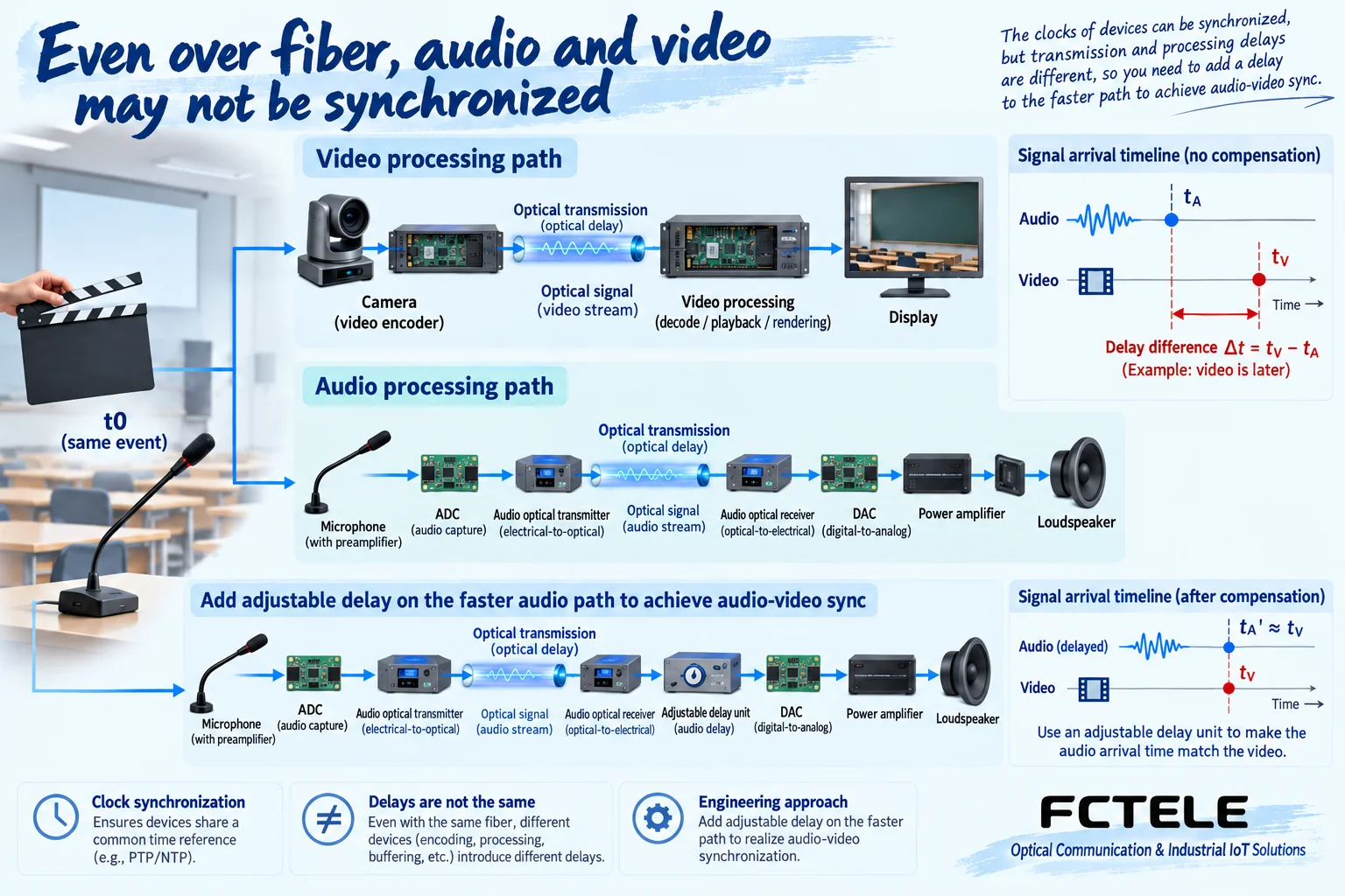
Clock synchronization concerns the pace at which samples are produced and played, while audio-video alignment concerns when the same event finally arrives. The two are related but cannot replace each other. For acceptance, a test event that produces both a visible action and sound at the same time can be used, recording the actual arrival times at the display end and the audio end. If the audio path is faster, delay can be added in a supported audio processing stage; if video is faster, the adjustment capability on the video side or system side must be evaluated. After changing the encoding mode, resolution, or effect processing, retesting is also required.
Conference interconnection also needs echo and routing design
Suppose two conference rooms each have a microphone and a speaker. After the remote sound is played through the local speaker, it may enter the local microphone again and be sent back to the remote end, forming echo or acoustic feedback. An audio optical transceiver mainly solves transmission and does not by default include acoustic echo cancellation. A suitable conference processing device should handle mixing, echo processing, and send bus arrangement, avoiding sending the remote incoming sound back to its original place without processing.
The same applies to remote teaching, enterprise conferences, and monitoring: the capture, monitoring, return, and recording channels must be written clearly separately. Pure audio equipment does not handle a camera’s video interface, nor does it automatically implement internet conference access. If crossing a network is required, compatible encoding, network services, and management schemes are needed, rather than putting an Ethernet plug on a dedicated optical transceiver.
How to check the network and optical link
For a dedicated optical link, check the line protocol, channel direction, optical port, single-fiber or dual-fiber operation, and optical power window; for networked audio, first confirm the endpoint protocol and sampling settings, then check the network topology, service bandwidth, clock, and routing according to the manufacturer’s requirements. If multicast services are used, the network’s support for multicast must be understood, but do not blindly change all switch options without understanding the system requirements.
Fiber can reduce electromagnetic coupling in the transmission segment; it cannot eliminate front-end noise or network configuration problems. Uncompressed also does not mean the analog end is absolutely lossless. For conferences that require confidentiality, fiber itself does not provide encryption; access control and encryption capabilities should be checked separately. For general applications, optical budget, and segment-by-segment troubleshooting, refer to Audio optical transceiver application and connection boundaries.
Acceptance must cover three types of results
First, verify the sound channel by channel: use an identifiable test source to confirm the source end, destination end, and left and right channels, and observe silence, noise floor, and overload conditions. Second, verify continuity: run according to the actual service, and check clock locking, buffering, and link fault indications; the test duration should be set by service requirements, not by using a brief listening test to prove long-term stability. Finally, test audio-video sync and two-way speaking at the same time, checking the delay difference, echo, and experience during switching.
Record the actual endpoint models, interfaces and protocols, sampling settings, channel map, network and fiber cable paths, measurement locations, and test conditions. In this way, when the system changes displays, adds effect processors, or upgrades encoding configurations, it is possible to know which items need to be accepted again. So-called technical progress is truly valuable when it clarifies applicable capabilities and verifiable boundaries, rather than stacking ever-higher rates or ever-longer distances.
Reference note: Architectural concepts refer to the above Dante official description, product connection categories refer to Feichang Technology official classification, and sampling and front-end mechanisms refer to TI audio ADC material. This article does not claim that Feichang Technology models have unverified Dante, MADI, or echo cancellation functions. The illustrations are general principle diagrams, not on-site measurements.
Translated from the Chinese technical article. Source first published: 2023-11-20. Source last revised: 2026-10-13T14:22:45+08:00. Read the Chinese source
