


Ethernet fiber transceivers are used to convert copper cable electrical port links into fiber links, to extend network connections or adapt to different cabling conditions. They mainly change the transmission medium and do not automatically become a router, protocol gateway, or PoE power supply. When selecting, the speed, fiber type, wavelength, and transmit/receive power conditions at both ends must be compatible.
Why fiber is still needed after network cables
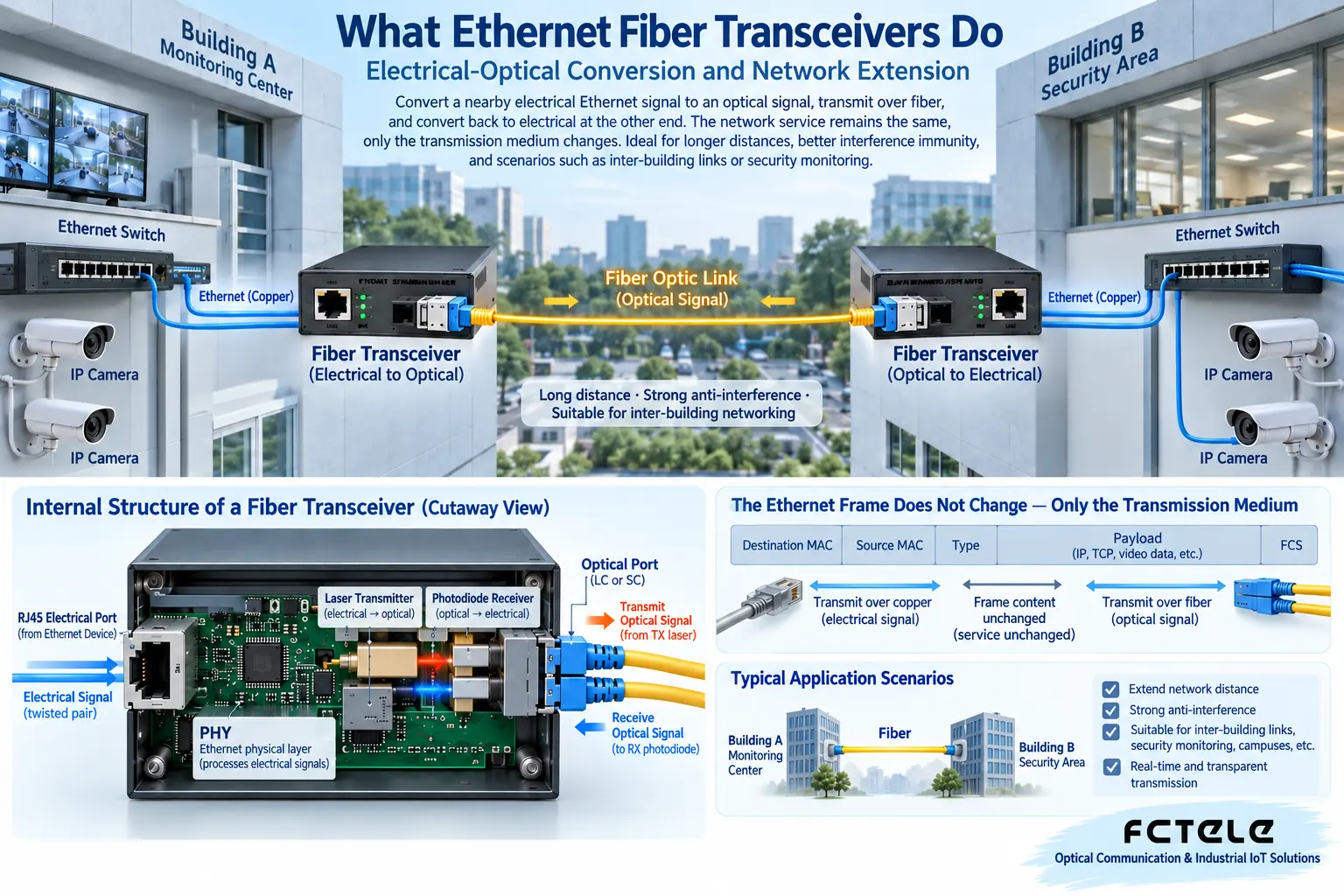
Terminals often have RJ45 electrical ports, but fiber may be more suitable across buildings, over long runs, or in environments with strong interference. A transceiver lets the terminal keep its original Ethernet interface, converts the signal to light in the middle, and restores it at the other end. Endpoint applications usually do not need to know how the intermediate medium changes.
Fiber has transmission characteristics different from copper, but the actual distance depends on the module, the fiber, and line loss. You cannot infer that any distance is usable just from “single-mode”; strong light over a short distance may also exceed the receive range. Engineering must consider both receiver sensitivity and the overload upper limit.
How the signal is turned into light inside the chassis
The electrical port receives an electrical signal, related circuits process the Ethernet physical layer or link information, and then drive the optical transmitter; on the receive side, optoelectronic devices convert the optical signal into an electrical signal. Whether direct conversion or a switched forwarding structure is used depends on the product implementation.
Ordinary media conversion maintains the network services it supports and is not responsible for directly turning video BNC or private serial protocols into Ethernet. Multiservice devices may have additional functions, but these should be checked item by item; you cannot treat every device called an “fiber optic transmission device” as the same kind of transceiver.
The two ends are not necessarily identical chassis
A transceiver can connect to a compatible transceiver and may also connect to a compatible optical port on a switch. Whether it works must be checked against protocol and optical parameters, not just whether the plug can be inserted. SC and LC describe connectors and cannot directly prove speed or service compatibility.
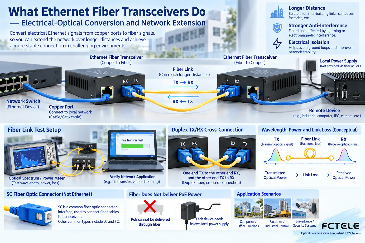
Dual fiber usually has TX at one end connected to RX at the other end. Single-fiber BiDi often uses complementary wavelengths to transmit and receive simultaneously; the wavelength sent by one end should be received by the other end. A/B names need to be combined with labels; you cannot assume A only transmits and B only receives, and you cannot pair the same wavelength combination arbitrarily.
Fiber can carry data, but it cannot automatically supply power
Remote cameras, transceivers, or switches need their own power supply, or use confirmed PoE devices on the appropriate copper segment. Fiber does not have the function of passing local PoE power through. After drawing the optical port link, the power supply paths at both ends should also be drawn separately.
Industrial sites also need to check temperature, installation, and protection conditions. A metal enclosure cannot directly prove waterproofing or wide temperature range, and ordinary desktop devices should not be unconditionally installed in outdoor cabinets. The applicable conditions of the device, power supply, and optical cable all affect long-term stability.
How to judge whether the connection is successful
First check power and optical link status, then check the electrical port link, speed, and actual application. Being able to Ping indicates partial network reachability and does not guarantee that camera streams, service ports, or continuous transmission are normal. VLANs, gateways, and access policies may still restrict upper-layer services.
Using a short link for isolated testing can reduce on-site variables, then connect the actual optical cable, measure optical power, and record error counts. Do not look directly into optical ports or observe with an unconfirmed optical microscope; handle end faces in the order of inspection, cleaning, and re-inspection.
How to form suitable selection conditions
Provide the supplier with the electrical port speed, optical cable type, core count, line loss, peer interface, and environment, rather than only asking “how many kilometers.” From Product Center check the specific model; acceptance includes service continuity, power-off recovery, and optical power margin, and does not use all indicator lights being on together as the standard.
During later expansion, the uplink shared bandwidth and power supply capacity must also be confirmed. Adding terminals may change the overall traffic, but it will not make the original single fiber suddenly gain capacity. Saving labels for ports, optical modules, and patch cords can significantly shorten troubleshooting time during maintenance.
Translated from the Chinese technical article. Source first published: 2020-07-17. Source last revised: 2026-10-13T20:58:17+08:00. Read the Chinese source
