


Correct use of industrial Ethernet fiber media converters includes compatible selection, proper installation, optoelectronic wiring, and real service verification; maintenance requires continuous recording of power supply, optical power, and error status. An industrial housing does not mean maintenance-free, nor can it prove that the device is suitable for all temperature, humidity, and interference environments.
Installation conditions come before plugging in cables
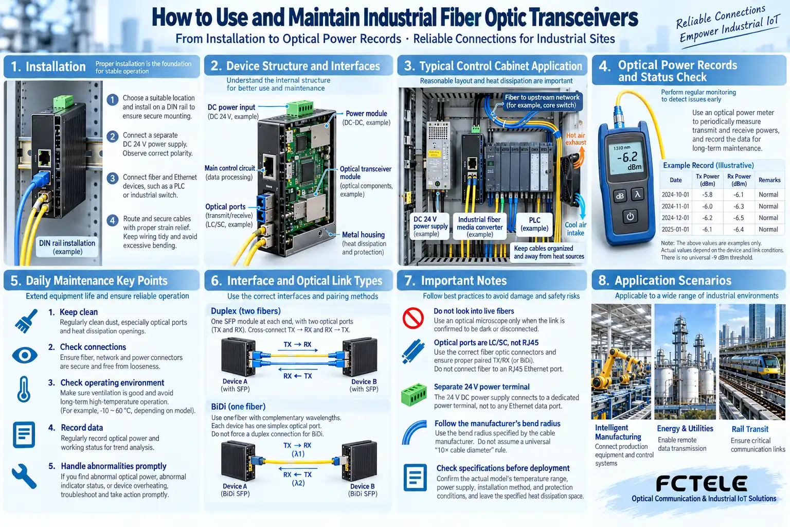
Check the actual model’s temperature range, power supply, installation, and protection conditions, and leave the specified heat dissipation space inside the cabinet. DIN-rail mounting parts should be securely fixed, cables need appropriate strain relief, and optical patch cords should not bear pulling force. The device’s nominal environmental conditions cannot replace an overall cabinet assessment.
Implement power polarity, protection, and grounding according to the manual and engineering design. Whether the two inputs are independent and how services recover after power loss need to be actually confirmed. Fiber only carries signals; the remote transceiver and terminal still need their own power supply plan.
Check both sides’ parameters before connecting
Confirm Ethernet protocol, rate, single-mode/multimode, single-fiber/dual-fiber, wavelength, and power range. For dual-fiber, TX connects to the opposite end’s RX; for single-fiber, pair according to complementary parameters. When connecting to a switch optical port, also check module compatibility; do not compare only the nominal distance.
The electrical port terminal and network configuration are equally important; confirm rate negotiation, VLAN, and address arrangements. A port light being on is only one status; it does not mean application data is being transmitted correctly. For initial commissioning, it is advisable to first test with a short link, then move to the on-site line.
Why endface cleaning affects stability
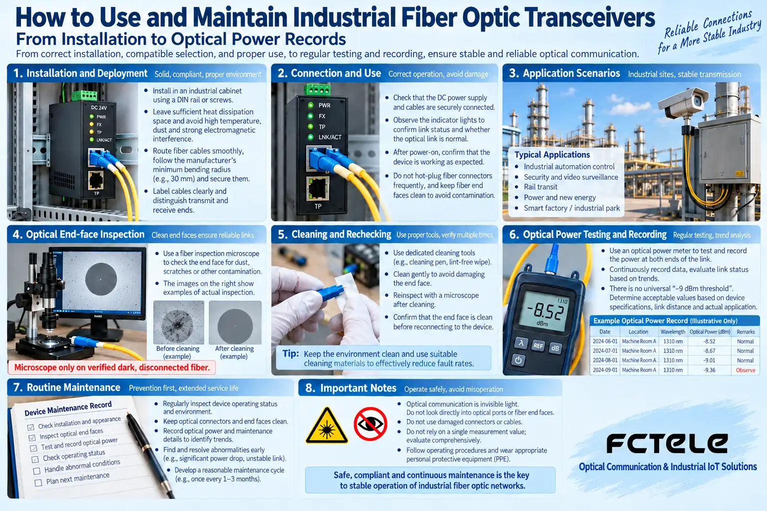
Dust, oil contamination, and damage can change connection loss or cause reflection. New patch cords and dust caps also cannot prove that the endface is definitely clean. Handle in the order of inspect, clean if necessary, then inspect again, and check both connected sides so contamination is not brought into another port.
Use tools suitable for the interface, follow laser safety and test equipment requirements, and do not look directly into the optical port. Cleaning methods should match the connector material and tools; do not touch the endface with your hands or repeatedly wipe at random. For specific principles, refer to Fluke endface inspection materials.
Keep a baseline record for the optical link
When putting it into use, record the models at both ends, wavelength, core number, received optical power, and error count. Power must be compared with that module’s receive range, avoiding both too weak and too strong. There is no single fixed normal power value that applies to all transceivers.
If an abnormality occurs later, it can be compared with the original baseline. If power has changed significantly, check connections, the line, and optical components; if power is stable but service fails, then check the electrical port, network, and application. Saving only “it could Ping at the time” is not enough to support later troubleshooting.
How to make daily inspections useful
Check cabinet temperature, device fixation, power alarms, cable bending, and labels, and review link errors and abnormal restarts. If on-site water ingress, dust, or temperature rise conditions change, evaluate the cabinet and power supply; do not simply replace the transceiver to cover up a system problem.
It is not recommended to repeatedly plug and unplug optical connections without reason. During a maintenance window, change only one item at a time and record the result; when necessary, use known compatible spare parts to isolate the issue. For unknown modules or firmware, confirm adaptation first; the appearance of a spare part cannot replace a complete parameter check.
How to hand over maintenance results
Keep the topology, core number, parameters, and measurements before and after the fault, and note replaced components and times. For actual Feichang Technology models, check the data through Product Center; after repair, verify continuous service and power-loss recovery, and do not use all lights being on together as the only acceptance criterion.
When production control is involved, operating permissions and shutdown arrangements should be clearly defined. An ordinary media converter does not automatically provide security isolation or encryption; network policies and management permissions still require system design. Stable device operation and service security are related but different maintenance goals.
The illustrations are schematic representations of scientific principles and application scenarios; the interfaces, structures, and measured values shown do not represent specific product parameters. Actual specifications must be based on model documentation and on-site measurements.
Translated from the Chinese technical article. Source first published: 2020-08-04. Source last revised: 2026-10-13T20:58:17+08:00. Read the Chinese source
