


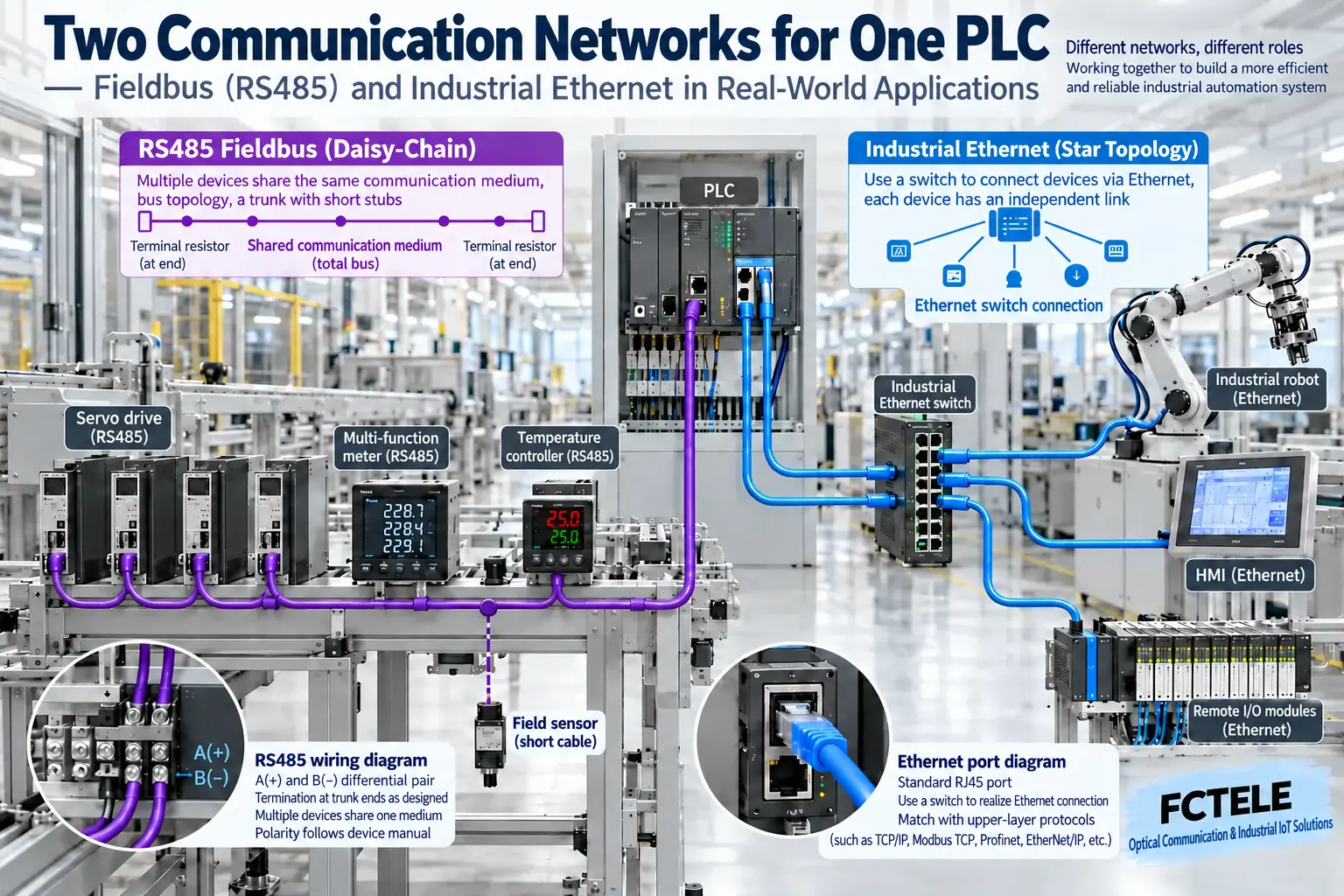
Fieldbus commonly uses a shared serial bus to connect controllers and field devices, while industrial Ethernet uses Ethernet as a foundation to carry industrial communication protocols. The difference between the two is not only speed; it also includes connection topology, access mechanisms, real-time behavior, diagnostics, and the engineering ecosystem. Switching to network cables will not automatically make old bus devices compatible; migration often requires protocol gateways, data mapping, and re-acceptance testing.
Understanding communication layers from a single “read temperature” task
After a sensor measures temperature, the controller needs to know the value, unit, status, and when it is updated. The wire only carries signals; the protocol defines how this data is expressed, and the application then decides how to use it. RS485 describes electrical connections and is not equal to a complete industrial protocol; protocols such as Modbus RTU and PROFIBUS also cannot directly interoperate just because they may both use serial lines.
Ethernet provides the foundation for frames and network connections, while industrial communication systems such as PROFINET, EtherNet/IP, and EtherCAT further arrange data exchange. They have different topologies, timing behavior, and device requirements, and not all protocols should be treated as completely identical IP messages on an ordinary switch.
The difference between sharing one bus and switched connections
A shared bus needs to manage who occupies the line and when to send, and the polling cycle is affected by the number of nodes, the amount of data per exchange, and retries. Daisy-chain wiring saves some cable, but one wiring point or trunk failure may affect multiple downstream nodes. Branch, termination, shielding, and connector specifications are part of engineering reliability.
Switched Ethernet can form multiple parallel port connections so that unrelated traffic does not all have to share the same wire. However, uplinks and device queues can still become bottlenecks, and broadcast, multicast, and large amounts of non-control data can also affect the network. Star is not the only topology; some industrial systems use line, ring, or specific connection rules, and protocol support requirements should be confirmed before choosing a switch.
“Fast” and “on time” are not the same metric
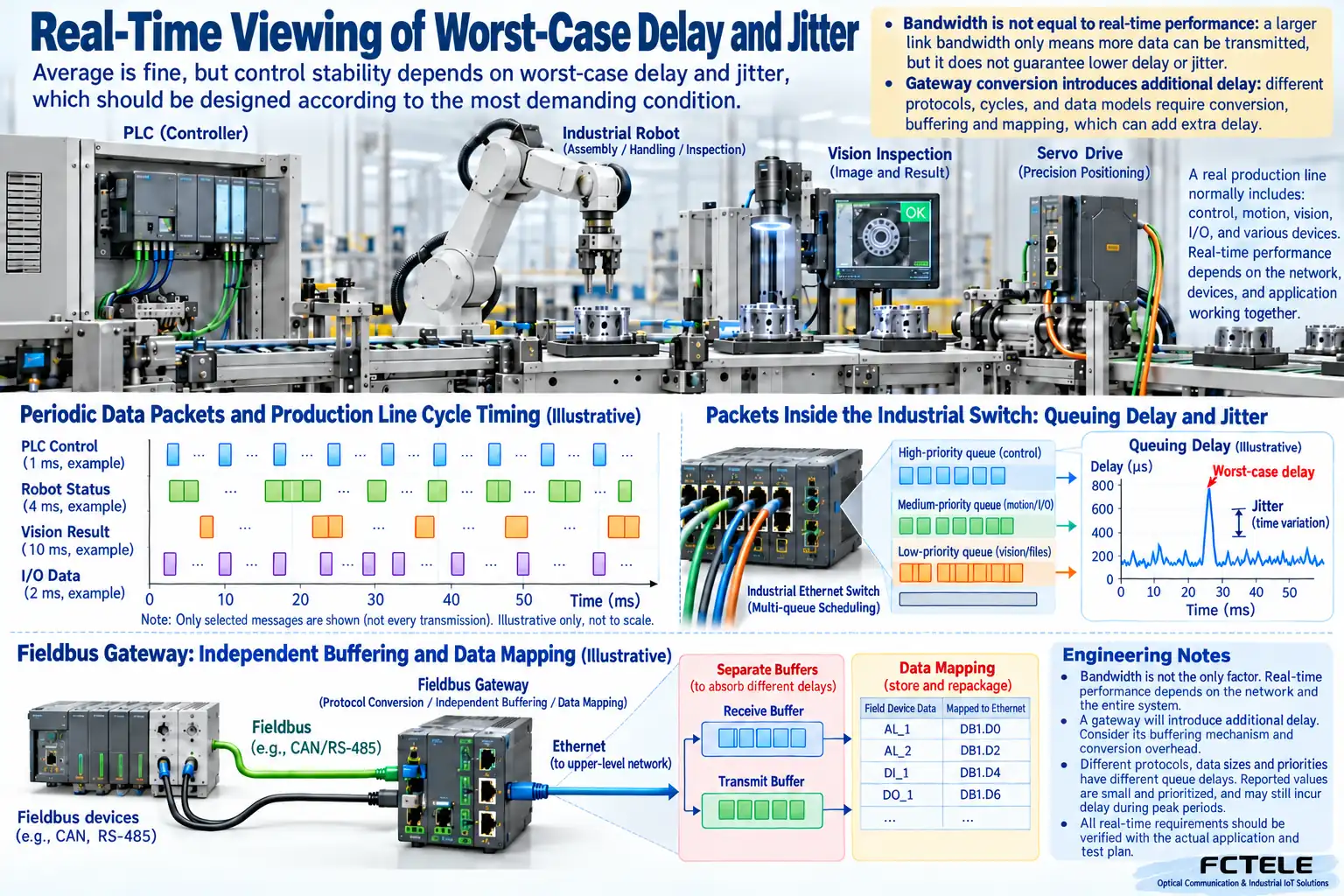
Bandwidth indicates how much data can be carried per unit of time, while real-time behavior focuses on whether data can arrive within a specified deadline. For example, average latency may be very low, but if it occasionally exceeds the control cycle, it may still cause alarms. Worst-case latency, jitter, cycle, synchronization accuracy, and fault recovery must all be considered; 100 Mbps or 1 Gbps alone cannot prove that motion control requirements can be met.
Different industrial Ethernet protocols improve timing behavior through different methods, and some requirements also involve dedicated hardware and synchronization mechanisms. Ordinary priority configuration can manage some contention, but it is not the same as achieving strict determinism; technologies such as TSN also require end-to-end system support and cannot be completed by merely adding one “high-speed switch.”
Upgrading old production lines: first preserve the correct meaning of the data
A gateway reads bus objects or registers and then maps them to the data model on the other side. Signed/unsigned, byte order, scaling, status bits, and update cycle must be checked. Seeing a number in the new system does not mean it is the correct temperature; whether an “old value” can be identified after disconnecting the sensor is equally important.
It is recommended to first choose a controllable area for a pilot and save the old program and wiring baseline. Test normal operation, full load, communication loss, and restart recovery separately; confirm how fault information is transmitted to the PLC and how the control program enters a safe state. Communication protocol migration should not arbitrarily change the functional safety scheme.
The two technologies can coexist for a long time
Existing equipment, maintenance personnel experience, and lifecycle often keep fieldbus valuable; areas that need centralized diagnostics, multi-service access, and information integration may be more suitable for industrial Ethernet. Evolving by area and business is usually more controllable than replacing the entire plant at once. When choosing, include protocol ecosystem, spare parts, software configuration, and security management in the total cost, rather than only comparing the number of interfaces.
Comparing diagnostic methods from a maintenance perspective
Fieldbus faults can be approached from master diagnostics, node addresses, line termination, and device status; industrial Ethernet can also observe port errors, negotiation, broadcast and multicast, topology, and link alarms. Adding diagnostic dimensions is useful, but it also requires maintenance personnel to understand network addresses and switching rules. Engineering delivery should include normal-state screenshots, topology, and executable troubleshooting methods.
For example, if a drive occasionally goes offline, do not directly replace the switch just because you see “network.” First compare the event time with link errors, device power, and protocol timeouts, then check load and update cycle. If the port remains normal but the PLC reports stale data, the focus may be on cycle configuration or application processing; if the link repeatedly disconnects, prioritize checking connectors, power supply, and environmental interference.
After connecting to the enterprise network, management permissions and cross-zone access must also be controlled. Industrial Ethernet brings convenience for information integration, but it also expands the boundary that needs protection; VLANs can organize broadcast domains, but they are not automatically equal to security isolation. Access policies, remote maintenance, and change management should be configured according to project risk, and control devices should not be casually exposed to office terminals.
Migration acceptance ultimately focuses on whether production requirements are met: data meaning is correct, update time is controllable, anomalies can be identified, and maintenance can be reproduced. A protocol being advertised as more advanced does not mean all existing equipment is worth replacing immediately; a suitable coexistence solution can also run stably.
References: PI: Differences between PROFIBUS and PROFINET ; PI: Fieldbus Integration Guide .
HART explains that analog and digital information can coexist
HART superimposes digital communication on a traditional 4-20 mA instrument loop; the analog value can continue to represent the process value, while the digital part is used for related parameters and diagnostic information. This is not treating an ordinary current line directly as an Ethernet cable, nor does the appearance of digital information mean the original analog loop must be removed. The host, interface, or gateway that needs to read HART information must support the corresponding communication; measuring only current does not mean digital diagnostic data has already been obtained. Verifiable FieldComm Group’s HART technical description .
Similarly, fieldbus and industrial Ethernet can often coexist for a long time according to tasks. Before migration, first list device protocols, data meanings, cycles, fault flags, and who initiates access, then check whether the gateway can map them correctly. Methods such as HART-IP can transmit corresponding information over IP networks, but this does not mean any serial server or switch automatically has that capability. The management system should simultaneously save the raw value, unit, and data validity status, clearly mark it unavailable after disconnection, and must not continuously display a cached value while treating it as a current measurement.
During acceptance, compare the real change on the end side with the change received by the upper layer, and check update time and disconnection recovery, not just verify port indicator lights. The upgrade plan should also retain fallback wiring, configuration, and data dictionary. Do not use old vendor lists, market forecasts, or judgments of inevitable decline to replace compatibility evidence for current equipment; which type of network to choose ultimately depends on the on-site business and maintainability.
The schematic is an illustration of general mechanisms, not a product test or model cross-section photo. Interface, protocol, protection, and power supply capabilities must be checked according to the actual model.
Translated from the Chinese technical article. Source first published: 2020-08-18. Source last revised: 2026-10-13T10:26:21+08:00. Read the Chinese source
