


The focus of industrial Ethernet development is not just more switch ports or higher speeds, but making production equipment reliably networked, manageable, measurable, and able to recover after a failure. To understand industry changes, start with on-site operations, environmental adaptability, protocol support, and system verification, and do not treat unverified brand rankings or market growth numbers as technical evidence.
Why factories need more network connections
PLCs and control systems exchange status, machine vision transmits images, equipment maintenance uploads diagnostic information, and production management systems gather data. These tasks have different data volumes, allowed delays, and continuity requirements. After connecting them to the network, you also need to arrange who communicates with whom and which faults must not affect each other.
The forwarding principle of ordinary Ethernet frames has not changed just because the scenario is a factory. The differences in industrial equipment are mainly in power supply, structure, environment, and management functions. DIN-rail mounting or a metal enclosure is only an external feature; actual temperature, EMC, and vibration capabilities need to be proven by model data and test conditions.
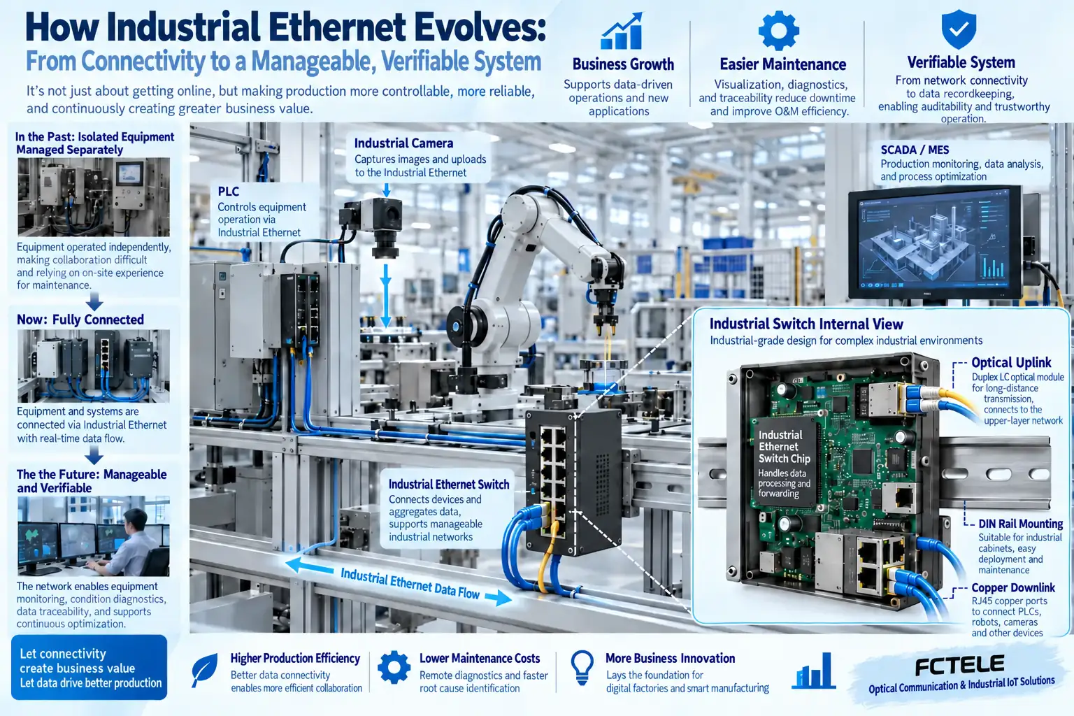
From being able to connect, to being able to manage
As the number of devices grows, you need to record port status, link errors, addresses, and configurations. Managed switches can provide corresponding diagnostic and management capabilities, but the specific protocols, permissions, and functions are determined by the model. Managed devices without a management plan can still become a black box during maintenance.
VLANs can divide broadcast domains, and access control can restrict the scope of communication; neither should be described as physical isolation. Network segmentation must also combine routing, management entry points, and upper-layer system permissions to avoid uncontrolled mixing of production traffic with guest or office networks.
Bandwidth and time performance are two different things
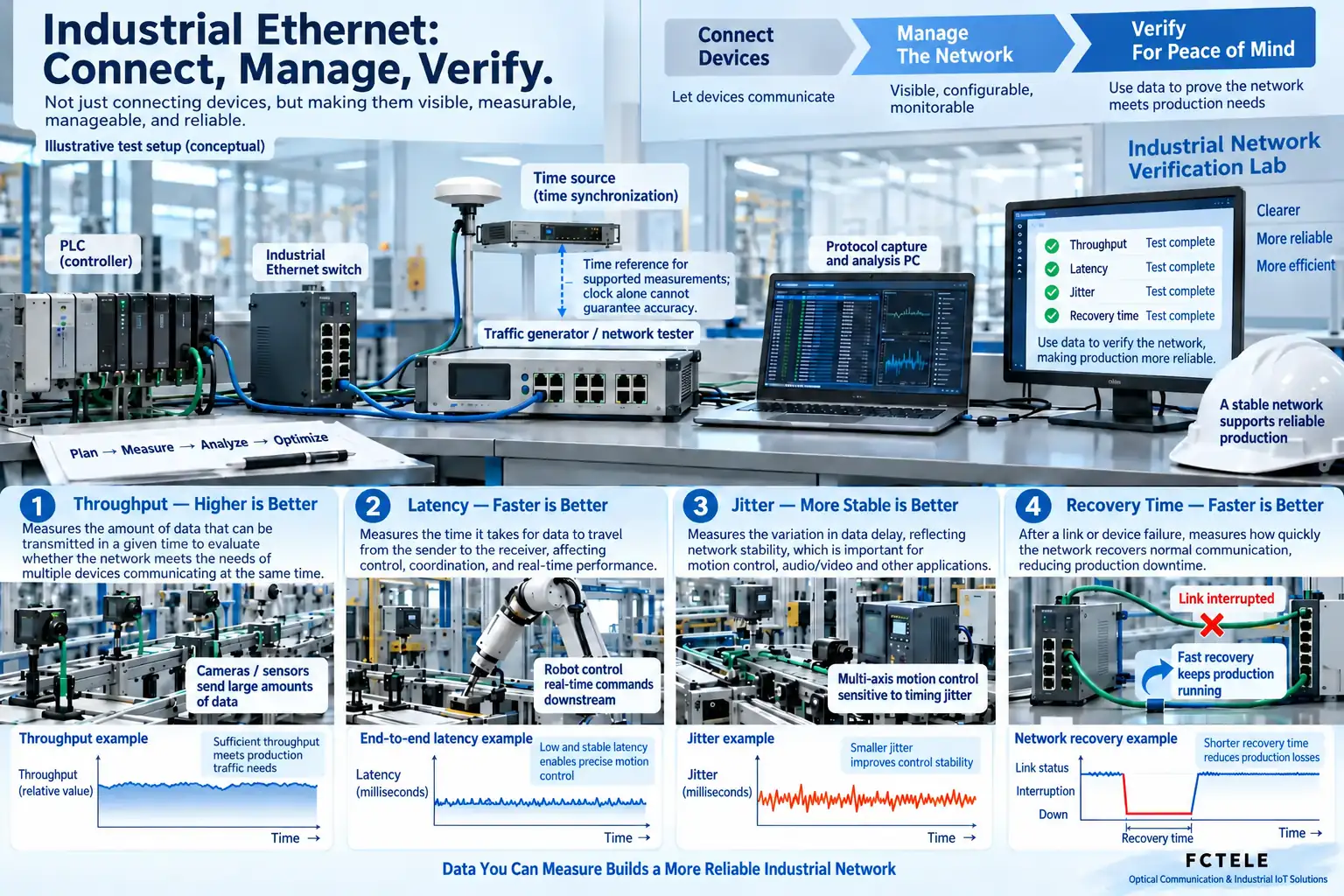
A gigabit link indicates nominal speed, not that every packet can arrive at a fixed time. Queuing, burst traffic, link sharing, and application processing can all increase latency. For control operations, latency, jitter, and packet loss are more meaningful than looking only at peak throughput.
Time synchronization, priority, and deterministic transmission are different mechanisms; supporting one function should not be understood as supporting all real-time requirements. If the system imposes strict timing requirements, confirm that devices, end systems, and protocol stacks work together completely, and measure under actual load.
Redundancy is not unconditional zero interruption
Adding backup links can improve availability, but it can also create loops at Layer 2. Correct redundancy protocols, port roles, and configurations are needed. Link fault detection, topology changes, and application reconnection all take time, so advertised recovery times should be checked against measurement conditions.
Power can also become a shared point of failure. If two inputs actually come from the same power source, they cannot be counted as independent power protection. Cabinet heat dissipation, cable routing, and maintenance permissions also affect operation, and reliability cannot be attributed only to one switch function.
How to read industry and brand information
Years, rankings, and market judgments in historical articles have time boundaries. Numbers without clear sources, statistical scope, and methods are not suitable for current procurement decisions. What is more comparable is evidence on interfaces, protocols, environmental testing, firmware maintenance, supply, and technical support.
When requesting a quote, provide on-site temperature, power supply, port requirements, fiber parameters, and business topology, and ask the supplier to specify the exact model that meets the conditions. Products from different brands should not be compared horizontally only by the words “industrial grade”; test standards and their scope of application should also be checked.
Turning development trends into executable plans
First define business goals, then plan segmentation, uplink, management, and recovery methods. Establish an acceptance baseline and save configurations, and compare the same test conditions for later expansion. Feichang Technology equipment can be found through Product Center to learn about models; technical selection should be based on actual functions and reproducible verification.
After continuous operation, you should also monitor error counts, temperature rise, and business anomalies, and distinguish network problems from end-device problems. Beyond procurement cost, spare parts, upgrades, on-site troubleshooting, and downtime costs together form maintenance cost, which is more useful for long-term use than a popular brand list lacking evidence.
Ethernet development does not mean fieldbus and DCS leave the site
DCS is a distributed control system, describing the system organization of control, monitoring, and engineering maintenance; Ethernet is a type of network technology that carries communications, and the two are not same-layer products that can directly replace each other. A DCS project can use Ethernet as part of its communication network, and can also continue to retain existing instrument loops and fieldbus. Fieldbus often handles communication between specific field devices, and its value needs to be judged together with protocols, device assets, control cycles, and maintenance conditions, not just by comparing nominal network port speeds.
Many sites have already invested in sensors, actuators, cables, control programs, and personnel training. Whether to migrate should first ask what the existing system specifically lacks: is it the large data volume of newly added cameras, a need for better device diagnostics, or a desire for upper-layer systems to obtain trustworthy production records. If the existing control loops meet requirements, replacing everything just to unify interfaces may increase downtime and new compatibility risks. You can let the old field network continue to control, use a suitable gateway to provide interpreted data to upper layers, and then gradually migrate the parts that truly need it.
Verify migration starting from one production line, not just drawing a networking blueprint
For example, a packaging line originally reported only equipment start/stop status, and now image inspection is to be added. First record the PLC control cycle, camera traffic, and existing bus load, and explain the requirements of image operations and critical control separately. Choose suitable access, aggregation, and isolation methods, then check whether the uplink is sufficient when multiple devices work at the same time. Isolation here may include VLANs and security policies, but VLANs themselves do not replace access control, and certainly do not automatically guarantee strict real-time performance.
When old equipment is connected through a gateway, you must record the name, unit, address, update time, and abnormal flag of each point. A number successfully delivered over the network does not mean the upper-layer software understands it. Degrees Celsius and raw count values, current values and historical cached values can all be misread. During the pilot, compare the actual state on the end side with the upper-layer display, actively create disconnections within the allowed range, and confirm that after loss of connection old values will not continue to be treated as real-time values, and that completed commands will not be executed again after recovery.
Migration acceptance includes normal load and the most unfavorable load. First save records of latency, packet loss, and data refresh during normal operation, then check network interruption, backup path activation, power restart, and configuration recovery item by item during a maintenance window. The fault location, test conditions, and business recovery criteria need to be stated; a very short link switchover time cannot represent recovery of the entire production line. For loops involving safety functions, handle them according to the requirements of the safety system itself, and do not rely on a general switched network to assume unverified safety responsibilities.
After the pilot passes, use the address plan, configuration backup, data dictionary, and maintenance process for subsequent expansion. Keep a fallback method for the old system, and clarify which step can restore the original wiring and control program. The value of Ethernet development lies in making suitable information easier to access, manage, and verify, not in declaring all old technologies obsolete. The schematic diagrams in this article show general scenarios and teaching measurement processes, and are not actual test results or proof of market share for any Feichang Technology model.
The schematic diagrams are illustrations of general mechanisms, not actual product tests or model cross-section photos. Interface, protocol, protection, and power supply capabilities must be checked against the actual model.
Translated from the Chinese technical article. Source first published: 2019-08-28. Source last revised: 2026-10-13T10:41:21+08:00. Read the Chinese source
