


When choosing a 10Gbps optical module, first check whether the switch port supports it, then match the fiber, optical port standard, and optical power at both ends.Buying a module labeled “10 Gigabit” does not mean it will work when inserted into any SFP slot. This article focuses on pluggable optical modules, especially 10G SFP+; it and a complete fiber transceiver with a network port and power supply are different purchasing objects.
1. First distinguish: buy an optical module, or buy a complete transceiver?
If the switch already has a supported SFP+ optical port and you want to connect to fiber, you usually need to choose a module and patch cord. If the terminal only has a network cable interface and the site needs to run fiber, you may need a complete optical-to-electrical conversion device. An optical module relies on the host for power and exchanges data with the host circuit; a complete transceiver also includes its own power supply, copper cable interface, and related processing circuits. Both are sometimes called “optical transceivers,” so when requesting a quote it is best to attach the host model, port photos, and business requirements.
SFP and SFP+ are similar in appearance, but appearance is not rate permission. What rate the host port supports, whether it accepts a certain type of module, and whether the firmware has restrictions must all be checked against the compatibility list. You cannot insert a 10G module into a Gigabit slot and assume the switch has been upgraded to 10G. The QSFP series involves more electrical lanes and different packages, and it cannot be treated as an upgrade replacement for SFP+ just by plug size.
2. How does the module convert electrical data into light?
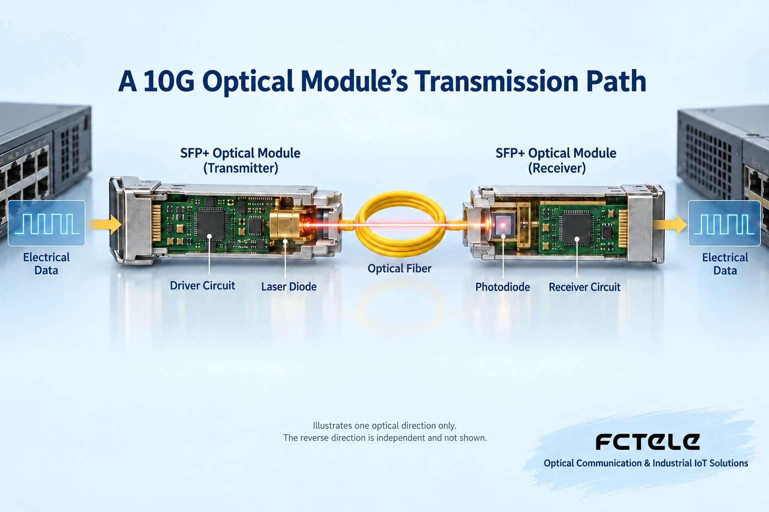
In the transmit direction, the host sends electrical data into the module, the driver circuit controls the laser so that the output light changes with the information, and then it is transmitted through the fiber. In the receive direction, the photodetector converts the received light changes into an electrical signal, and the receive circuit processes it and delivers it to the host. The actual encoding, signal processing, and internal integration vary with module design; the figure only shows the core relationship and does not represent the internal structure of a specific model.
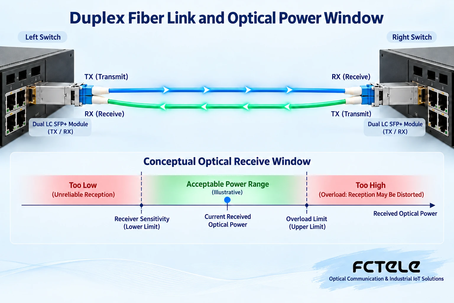
A common dual-LC duplex fiber module uses two optical channels: one for transmit and one for receive. The TX at the left end must connect to the RX at the right end, and the TX at the right end must connect to the RX at the left end, so that each direction can carry data. A bidirectional single-fiber module uses complementary wavelengths to transmit and receive on the same fiber core, and paired specifications must be selected; you cannot buy two modules with the same direction. The module will not automatically fix incorrect pairing, nor will it perform arbitrary protocol conversion for the switch.
3. How to choose SR or LR? First look at the existing fiber
SR and LR describe different optical interface operating conditions and cannot be understood merely as two price tiers for “short distance” and “long distance.” Common 10GBASE-SR uses multimode fiber, and 10GBASE-LR uses single-mode fiber. Fiber grade, wavelength, connector, rate, and interface standards at both ends must be checked together; distance is only one item.
As an example of public specifications, Cisco’s 10G SR module table lists OM3 up to 300 meters and OM4 up to 400 meters, and LR lists standard single-mode fiber at 10 kilometers. These are capabilities under the corresponding product and media conditions, not a guarantee for all brands or site links; if the existing multimode fiber is of a different grade, the 300 meters cannot be directly applied. This article does not treat these values as Feichang Technology product parameters.
One optical cable may have multiple fiber cores and may pass through patch panels, splices, and different patch cords. You should find out which two cores are actually used from one end to the other and whether the fiber type is continuously consistent; you cannot just look at the color of a short patch cord in the equipment room. LC or SC indicates the connector form, not whether the module is definitely single-mode, multimode, or a certain rate; the endface type must also match, and UPC and APC cannot be directly mated at will.
4. Beyond the nominal kilometers, the received power must be checked
Light attenuates as it travels through the fiber core, and connectors, splices, and other components add loss. At the receiving end, stronger light is not always better: it needs sufficient signal and also has an overload upper limit. Optical power falling within a suitable window is one necessary condition for the link to work, but it still does not mean that rate, encoding, host compatibility, and service configuration are all correct.
During design, use the module’s specified minimum transmit power and receive sensitivity to estimate the allowed loss, then deduct line, connector, and component losses and leave margin. For a very short link paired with a high-power long-distance module, the receive overload must also be checked against the maximum transmit condition. The two directions may have different parameters and should be calculated separately; you cannot test only one end and conclude that the entire link is qualified.
dBm represents the absolute level of optical power, while dB is often used to represent loss or a ratio; the two units cannot be mixed. For example, only as a calculation example: if transmit power is minus 5 dBm and path loss is 4 dB, then the estimated receive power is minus 9 dBm. Whether it is qualified still needs to be compared with the specific module’s receive range; the example does not represent any Feichang Technology module specification. On-site measurement should use suitable instruments, wavelength settings, and operating practices, and never look directly into the optical port.
5. Compatibility, temperature, and power consumption: why can’t they be asked last?
The switch being able to read the module model only indicates that part of the identification process is complete; it does not mean it is stable under all service loads. Confirm with the supplier the host model, hardware version, software version, port mode, and module coding requirements. When digital diagnostics are supported, temperature, power supply, and transmit/receive power can be viewed, but diagnostic readings and thresholds are based on the module implementation and cannot replace all instruments and service tests.
The module is installed in the host, and heat dissipation is affected by cabinet temperature, port density, and host airflow. The module’s specified operating temperature and storage temperature are different, and a switch marked with industrial temperature does not prove that any inserted module meets that range. When multiple ports are fully populated at the same time, especially check the host’s allowed per-module power consumption and overall heat dissipation conditions. A warm shell by touch cannot replace temperature diagnostics, and it certainly cannot be used to arbitrarily modify the device’s heat dissipation structure.
Hot swapping is a supported maintenance method, not permission to unplug and plug at will while services are running. Arrange a maintenance window according to the host manual, follow electrostatic protection, and correctly use the pull ring and dust cap; inspect the optical interface first, and if necessary clean it with suitable tools and then inspect again. Contamination increases loss and reflection; repeated plugging and unplugging may not solve the problem and may spread contamination.
6. Two scenarios to illustrate the selection order
Assume two switches in the same building need a 10G interconnection, the link is about 180 meters, and confirmed OM3 duplex fiber is already available. A 10G SR solution supported by the host can be evaluated, but the modules at both ends, the fiber type along the entire path, and connection loss should still be checked, and acceptance should be based on actual service testing. If the fiber grade is unknown, check the records or measure first; do not use “distance less than 300 meters” as the only basis.
Now assume about 2 kilometers of single-mode duplex fiber between two buildings in a factory area. A 10G LR combination supported by the host can be evaluated, and the power budget and overload conditions in both directions should be checked separately. If there is only one core, a compatible bidirectional single-fiber solution with complementary wavelengths needs to be evaluated, rather than leaving one line of a duplex module unused. These two examples are engineering approaches and cannot replace selection of a specific model.
7. How to compare Feichang Technology products, and what should be kept for delivery?
On the Feichang Technology official website, the managed industrial rack-mount 10G 4-optical 8-electrical Layer 3 switch, the product page lists 4 optical ports that can support multiple corresponding rates and 8 Gigabit RJ45 ports, and provides management functions such as SFP information reading. This port combination can help evaluate multiple fiber uplinks and local electrical port access, but each port rate, module model, and firmware support still need to be confirmed. The page’s use of SFP/SFP+ names should also be checked with the manufacturer and cannot be inferred from appearance.
Delivery records should at least include the host and module models, software version, rates at both ends, fiber type and core number, wavelength, connector, measured receive power, and load results. Testing should start with a short-link loopback test, then connect the site fiber, and record interface errors, throughput, packet loss, and reconnection status. A link light being on or a successful ping cannot prove stability at full load; when an abnormality occurs, change only one condition at a time to locate whether the problem is the module, line, port configuration, or service side.
Technical references:Cisco 10G SFP+ official specifications, Cisco module installation instructions and the above Feichang Technology product page. The schematic diagrams in this article were checked during production and are used for teaching general mechanisms; they are not actual Feichang Technology modules, internal designs, or proof of actual measurement.
Translated from the Chinese technical article. Source first published: 2023-11-24. Source last revised: 2026-10-13T20:24:48+08:00. Read the Chinese source
