


The key point of a multi-serial server is to map different field interfaces to the correct network channels. One network port can carry multiple serial services, but you cannot mix the wiring, serial parameters, and data of different channels together. First build a correspondence table of “device—serial port number—network entry—host computer object,” then wire and verify channel by channel. This is clearer than connecting everything at once and then troubleshooting.
1. How is a multi-serial server different from multiple RS485 slaves?
A four-serial server usually provides four serial interfaces, and each interface can connect to an independent terminal or bus according to the product configuration. A single RS485 serial port can also connect multiple slaves, provided that the protocol, addresses, topology, and electrical load allow it. Four independent serial ports and four slaves on the same bus are not the same structure.
For example, two access controllers use RS232, and another meter group uses RS485. They may occupy three separate channels in total, and each channel has a different interface, baud rate, and protocol. You cannot connect them all to one pair of RS485 terminals just because the devices are concentrated in the same box, and you cannot assume that all interfaces can freely switch electrical type.
2. How does one network port distinguish data from multiple serial ports?
Inside the device, independent transmit/receive and buffering can be configured for different serial ports, and the network side then distinguishes channels according to the configuration. Common implementations may use different listening ports, different connections, or vendor-defined encapsulation identifiers. Which one is used must be checked against the model and mode; you cannot treat “one serial port, one port” as a hard rule for all products.
Assume channel 1 and channel 2 are mapped to two example service ports. The computer must connect to the correct entry to send bytes to the corresponding serial port. If you connect to channel 1 but query the station number of a device on channel 2, the terminal will not automatically respond just because the network connection succeeded. Ports and station numbers are addresses at different layers.
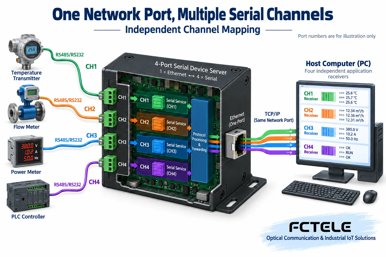
When building the correspondence table, record the terminal name, serial port number, interface standard, parameters, service protocol, and host software object. If virtual COM is used, also record the COM number and driver mapping; if a Socket program is used, record the connection and application device object. After reconnection or device replacement, check again to avoid historical configurations pointing to the wrong location.
3. Check the wiring separately for RS232 and RS485
RS232 commonly has transmit, receive, and reference terminals. When connecting, check the definitions on both sides; usually one side’s transmit corresponds to the other side’s receive. Whether flow control lines are needed and whether the cable is straight-through or crossover depends on the interface purpose and device type. You cannot judge only by whether the connector is male or female, and you must not connect RS232 signals to RS485 differential terminals.
RS485 should be wired according to the bus design, maintaining a continuous trunk and appropriate branches within the allowed topology. Termination and bias should be determined according to the actual devices and line. The A/B naming of different manufacturers may be inconsistent, so compare the electrical definitions rather than the letters or colors. Reference ground, shielding, and isolated grounding should be implemented according to the manual and site design; do not treat the schematic as a method for shorting any terminals.
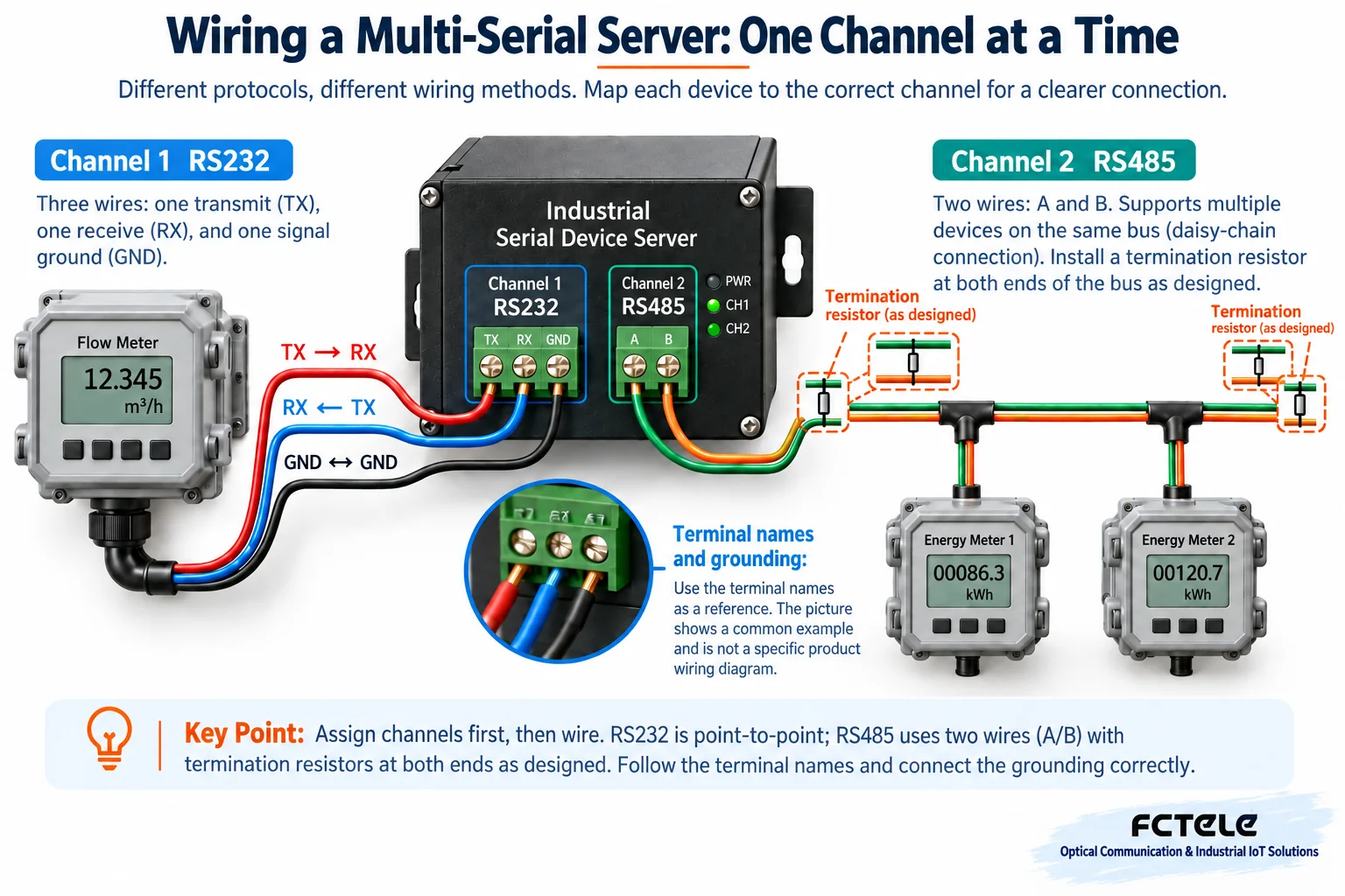
Slave addresses on the same RS485 bus should generally avoid conflicts according to the protocol; different independent channels may have the same station number, but the host software must distinguish them using the channel identity at the same time. The independent channel number itself does not prove that the ports are electrically isolated; the isolation structure and rated conditions must be checked separately.
4. Serial parameters for each channel must be saved separately
Baud rate, data bits, parity, stop bits, and flow control should match the corresponding terminal. Copying all four channels’ parameters to be the same only applies when the terminals actually require the same settings. The network rate is much higher than the serial rate, but it does not eliminate serial transmission time; when collecting multiple services at the same time, also check the device processing capability and buffering limits.
The host program should save parsing buffers and timeout states independently for each channel. TCP is an ordered byte stream, and one read may contain half a frame or multiple frames; the application restores messages according to that channel’s protocol. Data from different devices must not be mixed into one message queue that does not distinguish sources just because it is received on the same network port.
5. Choose the working mode according to the host software
When the host computer actively accesses the field, TCP Server can be considered; when the field actively connects to the center, TCP Client can be considered. Point-to-point paired transparent transmission requires matching roles and serial parameters at both ends. Virtual COM is used to support compatible legacy serial software, while Socket applications directly handle network connections; the two cannot be freely interchanged by just one “protocol option.”
Multiple computers accessing the same serial channel also require coordination. The number of network sessions does not equal the number of safe multi-master controls. Whether the device broadcasts replies, queues requests, or supports protocol arbitration should be checked against the actual mode. An old article that says it can connect to multiple platforms on one hand and cannot connect simultaneously on the other is a contradiction lacking a model premise and cannot continue to be used as a general conclusion.
6. Why does access control renovation still require service verification?
Connecting an old access controller to a serial server can change the data transmission path, but it will not automatically turn the old protocol into native IP access control. The management software still needs to support the terminal protocol and the corresponding network or virtual COM access, and authorization, time synchronization, and event reporting must also be checked.
For example, active event reporting and center polling may have different message rhythms. Whether events are buffered during disconnection and whether they are retransmitted after recovery affects record completeness. Actions such as opening a door also require confirming the execution state after timeout to avoid blind retries. Distance depends on the respective conditions of the serial segment and the network segment; you cannot promise that there will be no distance or reliability limits once connected to the network.
7. Verify channel by channel, not just the network port
In the test environment, first connect only channel 1, use a known good request to check bidirectional data and content, then test the remaining channels in sequence. You can have each device return distinguishable content to confirm that the names, readings, and physical objects in the software match. Then run them simultaneously and observe whether there is cross-channel mixing, response misidentification, timeout, and buffer growth.
Then test disconnecting one terminal, disconnecting the network, and restarting the device, and record the behavior of other channels and whether the configuration is retained. Separate physical ports do not mean that all faults are independent; power, processor, and network may still share resources. Acceptance should include overall load and fault recovery, not just short-term success on a single channel.
8. Confirm interfaces according to the ordered configuration
The Feichang Technology FCT-1500 series details provide different RS232, RS422, RS485, and three-in-one configurations, and also list switched electrical port and optical port options, which can be selected according to the terminal composition. Choosing a multi-channel device helps centralize access, but the actual number of channels, optional interfaces, and working modes must be checked against the complete model; you cannot treat the series range as the interfaces that every device has at the same time.
Before construction, save the correspondence table, wiring records, and normal request replies, and re-verify after device replacement. Only when the network channels, serial wiring, and service objects correspond accurately can the convenience of multi-channel integration truly serve maintenance, rather than adding difficult-to-trace mixed-line problems.
References:Feichang Technology FCT-1500 series details and ordering configurations;TCP specification. The illustrations are general principle diagrams and do not represent a specific product wiring table, physical object, or measured performance.
Translated from the Chinese technical article. Source first published: 2022-12-16. Source last revised: 2026-10-13T20:24:48+08:00. Read the Chinese source
