


RS232 and RS485 mainly describe how electrical signals are transmitted, Modbus describes how devices organize requests and understand data, and HART can superimpose digital communication on a compatible current loop. They are not four similar interfaces that can be directly interchanged. Before wiring, first distinguish the physical electrical conditions, the communication organization method and the meaning of the data, then choose matching devices. This can avoid many problems where a plug can be connected but no value can be read.
Look at a temperature acquisition process with a layered approach
The temperature sensor first turns the measurement result into data inside the device, then sends it out according to the corresponding rules. The electrical interface is responsible for sending the bits to the other end; the data rules tell the receiver which bytes are the address, which are the request, and which values represent temperature. If two devices are only connected by wires but understand the meaning of the data differently, correct acquisition still cannot be completed.
You can compare it to a transport vehicle and the content of a letter: the transport vehicle delivers the letter, but does not automatically translate the content into another language. However, this analogy cannot replace the actual specifications. Different electrical interfaces have voltage, reference and timing requirements, and different protocols also have address, check and response rules. On site, you should list the models at both ends, the interfaces and the supported protocols, rather than only asking whether there is a serial port.
How RS232 represents electrical signals
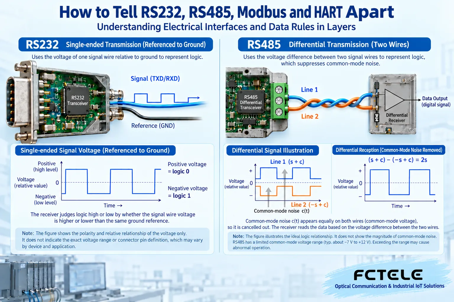
RS232 uses voltage relative to a signal reference to represent logic states. In common asynchronous serial applications, the transmit line, receive line and reference connection all have corresponding requirements; roles and connection definitions should be checked in the device documentation, and you cannot assume that all connectors with the same shape use the same pins. The role of a level converter is to make the corresponding interface meet compatible electrical conditions, not to automatically understand application data.
RS232 signals cannot be directly mixed with low-voltage logic serial ports. Interfaces described by names such as TTL may differ from RS232 in electrical conditions, and incorrect connection may cause communication failure or even damage. Line length and usable rate are affected by the device, cable and environment, and a common distance cannot be treated as a universal guarantee. When actual terminals and live measurements are involved, work should be performed by qualified personnel according to the manual.
Why RS485 uses the difference between two wires
An RS485 receiver mainly judges the state based on the voltage difference between two signal wires, rather than only looking at the voltage of one wire relative to a reference. If external interference causes the two wires to change in a similar way at the same time, the difference between the two wires may be less affected. This is why differential transmission helps suppress common interference. Twisted pair also helps the two wires face similar external conditions.
Differential does not mean unlimited immunity to interference. The receiver still has an allowed common-mode range, that is, the common voltage of the two wires relative to the device reference must be within the specified conditions. Wiring, shielding, reference connection, isolation and protection must all be designed according to site requirements. Labels such as A, B or positive and negative need to be checked in the device documentation, and the connection method cannot be judged only by letters, wire colors or experience with another brand.
Multiple devices sharing a bus also need communication order
RS485 can be used for multipoint connections, but the physical bus itself does not establish for all applications the rule of who sends first and who sends later. Common half-duplex applications take turns transmitting and receiving on the same pair of wires. If multiple devices drive the bus at the same time, conflicts may occur. Other transmit/receive structures also exist, and all RS485 cannot be described as having the same number of ports and working method.
Termination, biasing, stub length, node load, rate and distance together affect the link. You cannot multiply a certain maximum distance, maximum rate and maximum number of nodes and think they can all be achieved at the same time. This article explains why these conditions need to be checked, and does not provide specific resistance or wiring configurations across models. Actual design should be based on device documentation, bus specifications and on-site testing.
Modbus lets the receiver know the meaning of the bytes
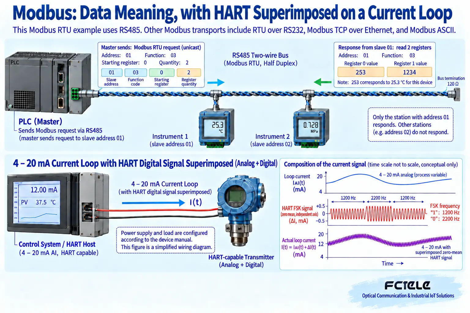
Taking Modbus RTU reading a meter as an example, the request contains the target address, function and the data range to be read. The specified device responds according to the rules, and the master then checks the response and interprets the values. The check is used to detect corresponding transmission errors, but even if the message passes the check, it does not prove that the register address, unit and data format are necessarily chosen correctly.
After reading an integer, it may still be necessary to consider scaling, decimal places, byte order or register combination method. These meanings come from the specific device data sheet, and are not automatically provided by the two RS485 wires. Modbus also has different bearer methods, such as Modbus TCP. Transparently carrying serial bytes and truly performing protocol conversion are different capabilities, and you cannot assume that a device can translate just because it has both a serial port and a network port.
How HART coexists with analog current
In a compatible traditional point-to-point HART loop, a digital communication signal can be superimposed on the 4-20mA analog current. The slowly changing analog current expresses the process variable, and the digital part uses different frequencies to express bits. The digital signal maintains corresponding average characteristics by design, so that the analog process variable and digital communication can coexist under specified conditions, rather than directly turning the original current into another unrelated interface.
The premise here is that the instrument, host, loop load and other connections all meet HART requirements. Ordinary analog input or transmission equipment marked only 4-20mA may not retain or support HART digital communication. Isolators, converters and optical transmission links also need compatibility checks, and you cannot claim that superimposed digital information can be transmitted unconditionally just because analog current can be transmitted.
When choosing a conversion device, first ask which layer it converts
An interface conversion device may only change the electrical method, a transparent transmission device may carry bytes to a remote end through a network or optical fiber, and a protocol gateway may map one kind of request to another. All three kinds of work may be called conversion, but the items that need to be checked are different. The first two usually still require both application ends to understand the same data, while the latter also requires correct parameter mapping.
The serial interface converter details on the Feichang Technology website can serve as an entry point for checking actual interface capabilities. For example, for a model with USB and corresponding serial functions, the driver, interface version and usage conditions need to be confirmed, and it cannot be understood as a gateway that automatically converts all industrial protocols. When choosing a serial server or protocol device, the corresponding details and delivery materials should also be read separately, and functions cannot be inferred across product categories.
An example where meter data cannot be read
Suppose a computer is connected to an RS485 meter through a converter, but there is no response all along. First confirm that the computer is using a matching converter and that the electrical conditions of the meter and converter are correct, then check the baud rate, character format and transmit/receive direction on both sides. Then check whether the request is sent to the correct address, and whether the function and register range belong to this meter. Do not conclude at the beginning that the meter is broken.
If a response is received but the value is unreasonable, it means the focus of troubleshooting may have shifted to units, scaling and data interpretation; if there is no valid response, it is still necessary to distinguish between wiring, settings and request rules. Change only one condition at a time, save the transmit and receive records, and then compare them with the device documentation. Do not short-circuit unknown live terminals just to try a connection, and do not modify multiple parameters at the same time and then treat an accidental success as a reliable conclusion.
Acceptance must prove both the wiring and the data clearly
After completing the connection, check continuous acquisition, abnormal response handling and recovery performance. Confirm that what is read is the correct data of the target device, and that the unit and update cycle meet the requirements, rather than only proving that a certain number appears in the software interface. Important control sites should be tested under authorized maintenance conditions, and unknown registers must not be written to devices at will.
Keep the models at both ends, the interface relationship, protocol parameters and data sheet version. Understand RS232 and RS485 as mainly involving electrical transmission, Modbus as data communication rules, and HART as a mechanism for coexistence of analog and digital on a compatible loop. This will help avoid mixing concepts and more accurately choose conversion, transmission or protocol mapping devices.
Verification materials:TI RS485 Design Guide;Modbus over Serial Line Specification;FieldComm HART;Feichang Technology serial interface converters. The diagrams explain general mechanisms and are not wiring diagrams for specific models.
Translated from the Chinese technical article. Source first published: 2023-10-17. Source last revised: 2026-10-13T20:37:04+08:00. Read the Chinese source
