


When choosing a serial server, do not start by comparing CPU bit width or the words “industrial grade.” Write down the site device interfaces, serial parameters, host computer access method, data volume, and installation environment clearly, then use a sample unit to verify continuous communication and disconnection recovery. A 100 Mbps Ethernet port cannot make a 9600 baud instrument faster, and a large buffer cannot endlessly absorb continuously excessive data. A suitable product is one that can meet the actual business needs and is easy to maintain.
1. First confirm what data it needs to carry
A serial server sends the serial bytes received from RS232, RS422, or RS485 devices into the network, and also sends bytes received from the network back to the serial port. Transparent transmission is like a carrying channel; it usually does not understand each value or control command. Converting Modbus RTU to Modbus TCP involves application protocol processing, and you cannot assume support just because a device has a serial port and an Ethernet port. Before purchasing, ask: does the original software need a virtual COM port, or does it directly use a network connection? Is transparent carrying needed, or specified protocol conversion?
A virtual serial port is a COM port simulated on a computer by a driver, so the original serial software can continue to use it; TCP client or server mode defines who actively establishes the network connection. These network roles are not the same as the master or slave roles of field instruments. Multiple computers being able to connect to the server at the same time does not mean they can freely send commands to the same RS485 bus at the same time. Multiple requests still need scheduling, otherwise conflicts may occur or responses may be misinterpreted.
2. Interface names and parameters must be checked separately
RS232, RS422, and RS485 are different electrical interfaces and cannot replace each other by changing the baud rate. DB9 connectors or terminal blocks that look the same may also have different definitions. RS232 usually involves transmit, receive, and signal reference; two-wire half-duplex RS485 takes turns transmitting and receiving on one pair of wires. For specific terminal names, reference ground, shielding, and isolation requirements, check both sides’ manuals; do not blindly wire according to photos on the internet. A three-in-one device provides convenience of choice, but usually requires explicitly selecting the interface type rather than letting all formats work at the same time.
Then check the baud rate, data bits, parity, stop bits, and flow control. Baud rate describes the serial symbol transmission rhythm, not the Ethernet port speed; for a common binary UART, the serial bit rate can be estimated from it. When an instrument requires a special baud rate or Mark, Space parity, you must confirm that the device supports it and actually test it. Do not understand “customizable” as meaning any value can be accurately generated; clock division and allowed error still have limits.
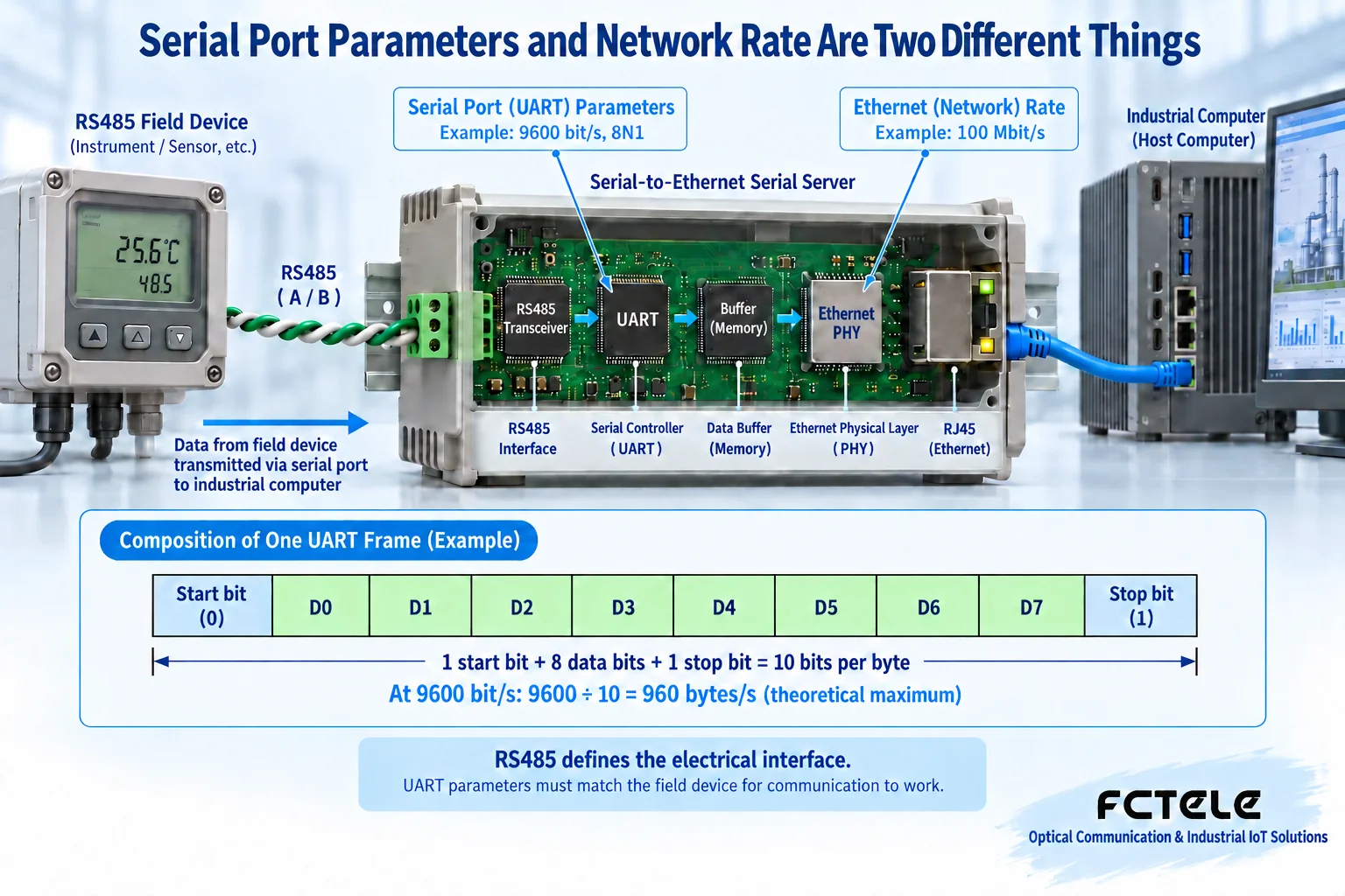
3. Why a 100 Mbps network cannot eliminate the serial bottleneck
In the 8N1 setting, in addition to the eight data bits of a byte, one start bit and one stop bit are also needed, so sending one byte occupies ten bit times. Dividing 9600 bit/s by ten gives an ideal upper limit of about 960 bytes per second. One thousand bytes takes about 1.04 seconds just for serial transmission, without adding instrument response, inter-frame waiting, and network time. Upgrading the Ethernet port to 100 Mbps or 1 Gbps cannot shorten this period of time, which is already determined by the serial rate.
Therefore, selection should count normal and burst data volume, allowed collection period, and maximum response time, not just look at the maximum baud rate. When a field device only supports 9600, setting the server to 115200 will prevent both sides from communicating correctly. After raising it to a parameter supported by both sides, also check wiring, distance, and bit errors. When the collection system has multiple instruments, the request, response, and waiting times also need to be added together; you cannot estimate the whole round time using only the byte count of a single message.
4. Buffering solves bursts, not permanent overload
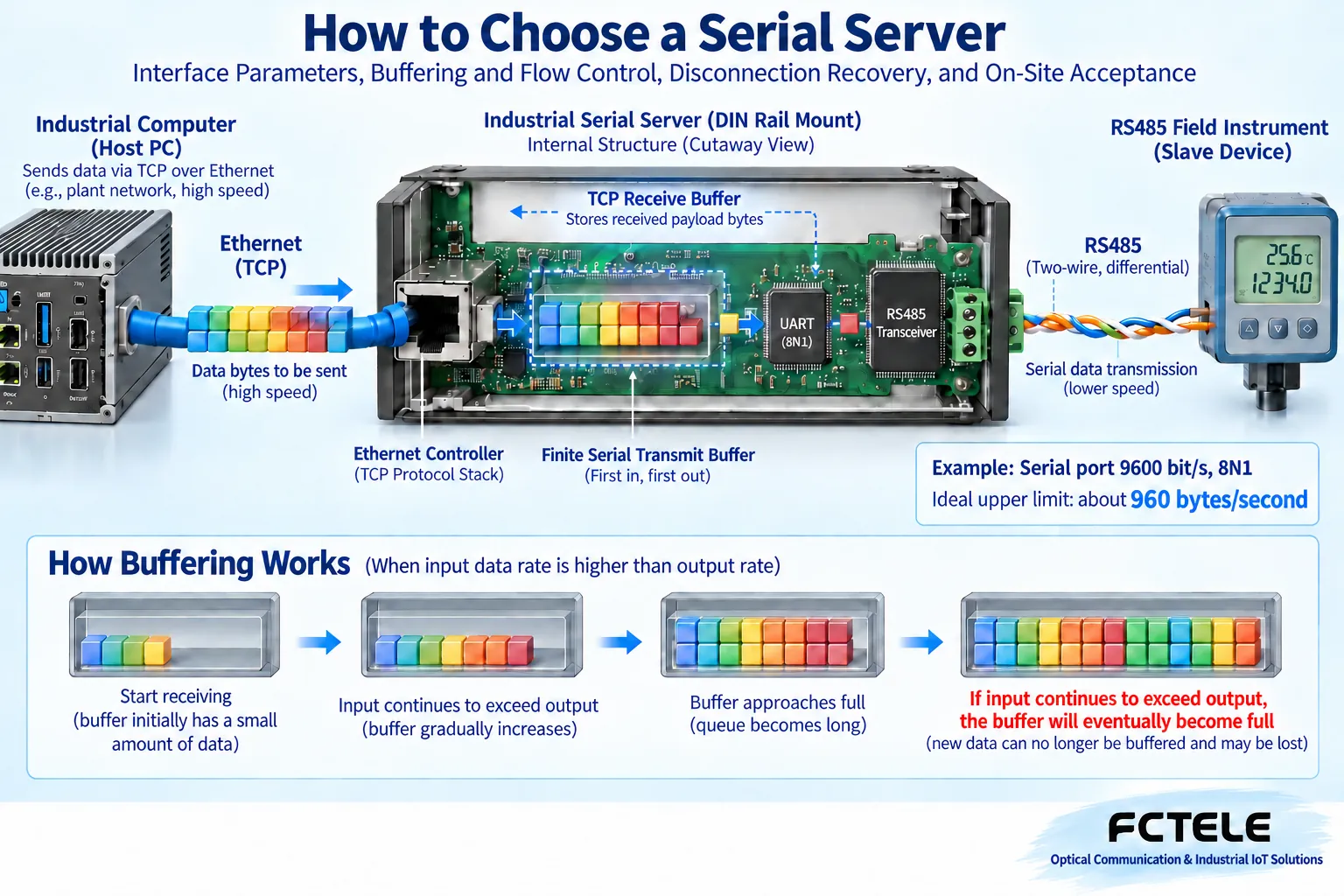
A computer may quickly send a batch of data to the network, while the serial port can only output byte by byte. A buffer is the limited space where the device temporarily stores data not yet processed, similar to a queue waiting to be sent. A short burst can be absorbed by the queue, but if the continuous arrival rate is greater than the sending rate, any finite queue will eventually fill up. A large buffer may increase burst tolerance, but it may also increase queuing wait time; “the larger the buffer, the lower the latency” cannot be taken as a rule.
TCP’s receive window is used to tell the peer how much data it can still receive; only when the device correctly coordinates this feedback with the internal buffer can the sender wait when needed. UDP does not have TCP’s flow control, so how excessive input is handled should be made clearer. Whether the serial side can use hardware or software flow control also depends on the interface, instrument, and application protocol. When purchasing, ask clearly about the behavior when the buffer is full, whether exceptions can be counted, and how data is handled during disconnection.
5. Measure latency across the whole link, not from a single advertised number
The wait for one collection may come from server framing, network queuing, virtual serial port driver, serial transmission, instrument processing, and host computer scheduling. If the framing timer is too long, it waits for more bytes before sending a packet; if too short, it may increase the number of small packets. TCP is also a byte stream and does not guarantee that one send corresponds to one receive, so the application must identify complete messages according to the protocol. When a timeout occurs, locate which segment consumes the time instead of directly asserting that the CPU or protocol stack “is not good enough.”
Use real messages, a real number of devices, and the actual collection period to record the distribution of time from sending a request to receiving the complete response. Look at both the average and clearly slow cases, and confirm data integrity, order, and business meaning. A no-load sample test or an old vendor claim of “below some number of milliseconds” cannot be treated as a promise under all site conditions. For control services requiring strict cycles, the timing boundaries of ordinary Ethernet and general-purpose operating systems should be evaluated even more.
6. Disconnection recovery cannot rely on repeated on-site restarts
Unplugging a cable, restarting a switch, or exiting the host computer may cause both ends to temporarily judge the connection state differently. TCP keepalive, application heartbeat, connection timeout, and reconnection strategy do not solve exactly the same problems; they should be set and tested according to actual supported capabilities. Keepalive probing the network connection is not the same as confirming that the instrument has executed a command; only when the application receives a clear response is there corresponding business evidence. A device being pingable only proves that part of the network function is reachable, not that the serial business thread is normal.
In an authorized maintenance environment, separately test network disconnection, peer exit, and reconnection. Confirm that the old connection can be properly released, a new connection can be established, and the serial business can recover without manual restart, and record whether data is lost, backlogged, or repeatedly executed during recovery. Write and control commands must not be blindly resent; the application should handle the case where execution has occurred but the response is lost. Supporting DHCP or DNS is not complete proof of TCP implementation quality; the real acceptance is still a repeatable business test.
7. For industrial sites, look at the whole unit, not CPU bit width as a substitute for evidence
An 8-bit or 32-bit processor is only one piece of design information; overall performance is also affected by software, buffering, drivers, power supply, and heat dissipation. Where the chip comes from and how many pins it has also cannot directly prove long-term stability. Ethernet port 10/100 rate negotiation and Auto-MDI/MDIX automatic crossover are different functions: the former negotiates connection capability, while the latter handles the transmit/receive wire pair relationship; they should be confirmed separately in the specifications.
Operating temperature should be based on the whole-unit rated range of the specific model, and the internal temperature rise of an enclosed cabinet should be considered, not just outdoor weather. Wide temperature does not mean waterproof, condensation-proof, or salt-spray resistant; lightning protection also does not mean grounding and external protection can be ignored. A wide-voltage power supply specifies the allowed supply range and does not promise to withstand any spike. Record the site power and installation conditions, configure suitable power and protection according to the manual, and leave inspections involving hazardous voltages to qualified personnel; do not create extreme voltages yourself to test the device.
8. With Feichang Technology products, turn purchasing requirements into specific items
The official details of the Feichang Technology FCT-081219 list one channel selectable RS232, RS422, or RS485 to 100 Mbps Ethernet, and provide functions such as WEB configuration, serial parameter and status monitoring, framing settings, virtual serial port driver, and automatic connection recovery after network interruption. Its DIN-rail or wall-mount installation and compact shape suit scenarios where one device needs to be connected within limited cabinet space. These are a starting point for checking functions, not a replacement for actual sample acceptance.
The same details also state that serial rate capability differs by interface, and the maximum value cannot be directly applied to RS232; DC power supply and whole-unit temperature range are also listed. When purchasing, ask the supplier to provide parameters according to the specific order model, firmware, and interface, and confirm the actually required baud rate, parity, concurrent sessions, driver system compatibility, and upgrade method. For multi-port collection, special isolation, or protocol conversion needs, check the corresponding model again; do not infer that an entire product category supports everything from a single-channel product.
9. Keep purchasing acceptance records that can be rechecked
Take a hypothetical scenario: the original collection software only recognizes COM ports, and several RS485 instruments need to be read over the network. First confirm the system version of the software and driver, check the bus topology and request scheduling; after verifying on a short local link, connect to the site network. Test normal load, reasonable business bursts, and disconnection recovery, and record collection success rate, response time, and exception handling; do not casually conduct stress attacks or shut down all firewalls at the production site.
Finally record the model, firmware, serial parameters, network mode, test messages, power environment, and recovery steps, and back up a configuration that can be rolled back. Ask clearly about technical support, firmware maintenance, and fault replacement arrangements. Interfaces matching, data volume being bearable, faults being recoverable, and maintenance being transferable are the complete answer to serial server selection; a single CPU label, imported chip, or higher Ethernet port speed cannot replace this evidence.
Translated from the Chinese technical article. Source first published: 2022-05-17. Source last revised: 2026-10-13T20:24:48+08:00. Read the Chinese source
