


In the context of Ethernet products, “Ethernet fiber media converter” and “optoelectronic converter” are often used to describe equipment that converts between electrical ports and optical ports. But optoelectronic conversion is a broader technical concept, and other business products may also be named this way. To judge whether they are the same type, you must look at the input and output interfaces, protocol, direction, and processing method.
Why the same device has two names
“Transceiver” emphasizes sending and receiving, while “optoelectronic converter” emphasizes the change between electrical signals and optical signals. For ordinary Ethernet electrical-port-to-optical-port equipment, the two terms often point to similar functions. The name itself, however, cannot determine the rate, fiber type, number of ports, or whether management functions are present.
Therefore, when asking for a quote, it is best to write it completely: Ethernet Ethernet fiber media converter, which kind of electrical port, which kind of optical port, what rate and fiber type. If you only say “optoelectronic converter,” the supplier may understand it as another kind of video, serial, or dedicated signal equipment, causing a mismatch in specifications.
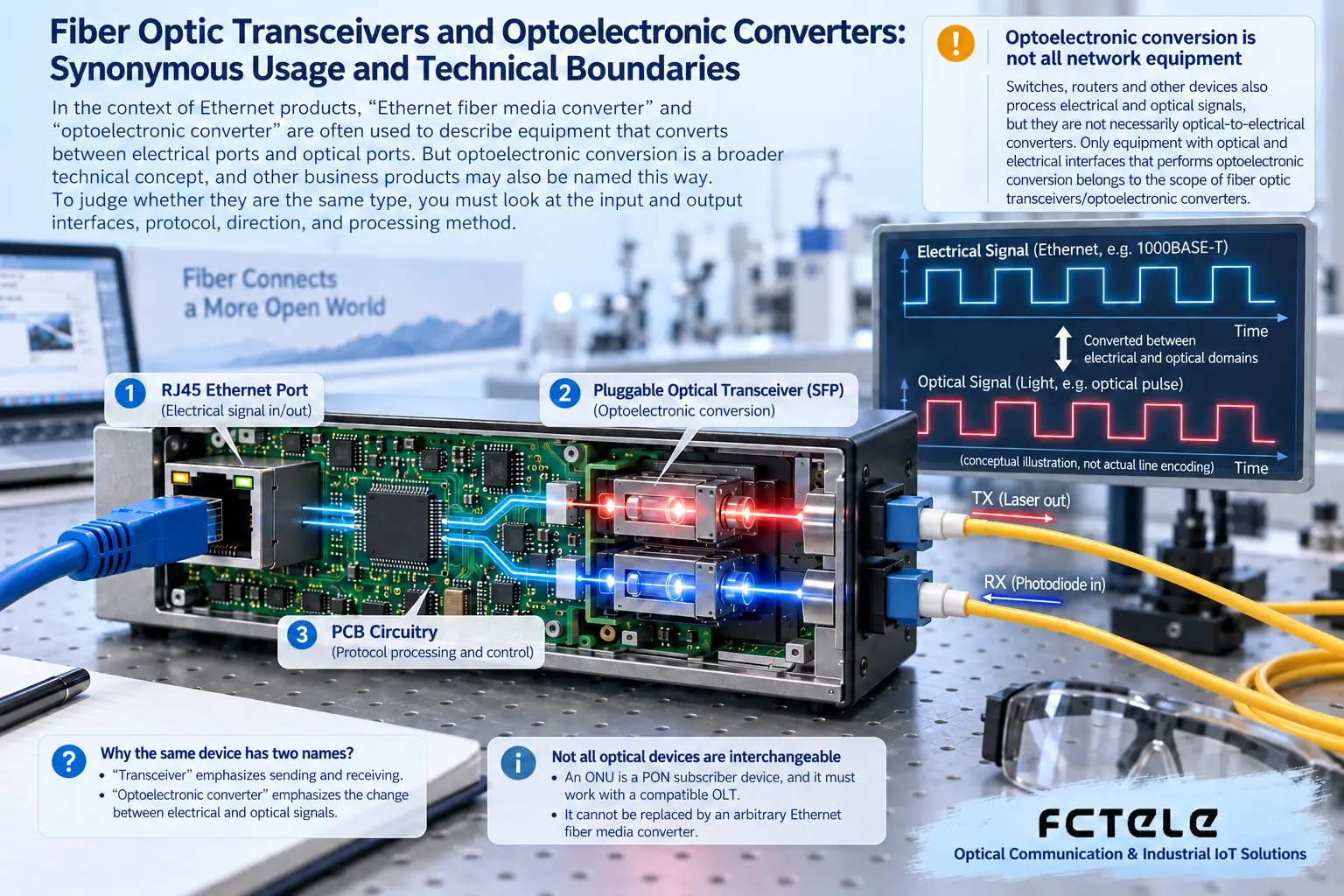
Looking at functional boundaries from the internal process
The electrical port side receives a compatible Ethernet signal, and the device transmits it toward the optical port, where the optical transmitter converts the electrical information into light; the receiving direction is the opposite. Different products may use different forwarding and buffering designs internally, and multi-port products may also have switching functions, so the internal structure cannot be inferred from the name alone.
This kind of conversion usually does not generate an IP address for the terminal or translate application commands. The network configuration of PLCs, computers, and cameras is still handled by the terminals and related network equipment. Changing to fiber can change the medium and distance conditions, but it will not automatically fix wrong VLANs, gateways, or authentication.
Single-fiber bidirectional and dual-fiber bidirectional
Dual-fiber solutions generally use one fiber for sending and one for receiving, and when connecting, one end’s TX should correspond to the other end’s RX. Single-fiber BiDi carries two directions through different wavelengths, and complementary transmit and receive configurations must be used. The A and B markings help identify pairing, but their specific wavelength relationship cannot be guessed without documentation.
The two ends may have the same interface shape but still have different wavelengths, rates, or optical standards; single-mode, multimode, and receive ranges must all be checked. You cannot compare only the nominal distance of the devices, nor assume that an end marked with a longer distance is necessarily better than the original matching end.
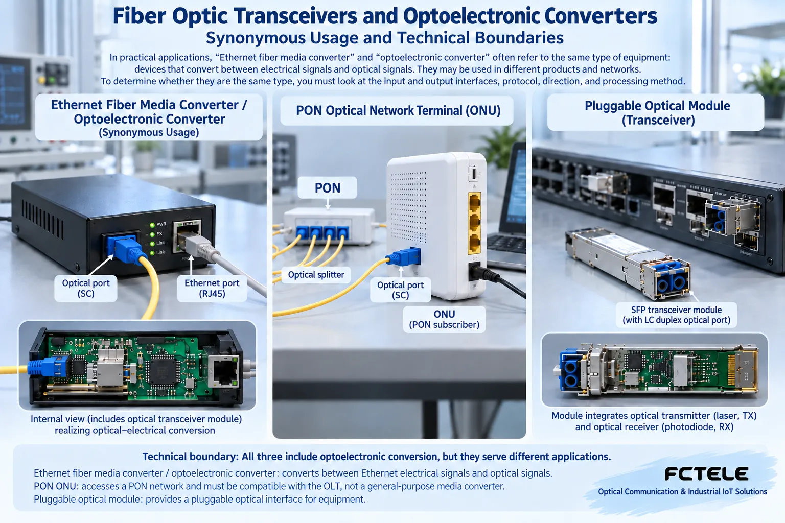
Do not confuse three similar products
Carrier optical modems usually handle PON access and involve the corresponding standard and certification; ordinary point-to-point Ethernet transceivers cannot replace them by default. Dedicated video fiber optic transmission devices handle the corresponding video format, and they cannot directly connect to IP network cameras just because they have an optical interface.
Serial fiber optic transmission devices and serial servers handle serial interfaces or networked carriage, and RS485 access cannot be turned into ordinary Ethernet service through a passive adapter. Interfaces, data encapsulation, and application protocols belong to different layers, and corresponding equipment is needed to handle the task.
When comparing parameters, do not be misled by names
Confirm the electrical port rate and negotiation, optical standard and module configuration, allowed frame length, VLAN transparency, and fault linkage behavior. For multi-port devices, ask whether capacity is shared; for PoE models, ask which ports supply power and what the total budget is. Capabilities not written in the documentation should not be inferred from the name alone.
Environmental parameters should also be checked against actual temperature, input power, grounding, installation heat dissipation, and test conditions. A metal housing does not automatically mean it meets industrial environments; certifications of other models from the equipment manufacturer cannot be used as evidence for this device.
The most practical way to identify
Look at interface photos, the complete model number, and the manual, then describe the requirement as “what devices are at both ends — what signal is transmitted — through what medium — what processing is needed.” If the answer is only media conversion compatible with Ethernet, the two names may refer to the same type; if business conversion is also involved, further distinction is needed.
For usage methods, refer to Transceiver pairing and service acceptance. After installation, the optical link, electrical link, and real application should be verified at the same time; the power light or optical port light being on cannot be regarded as all functions being normal.
Translated from the Chinese technical article. Source first published: 2020-08-06. Source last revised: 2026-10-13T20:58:17+08:00. Read the Chinese source
