


Using an industrial switch correctly is not just about plugging in the power and network cables, and it is not about turning on all advanced features. It is responsible for forwarding Ethernet data between devices; whether it has management, ring networking, PoE, or dual power supplies depends on the specific model. This article starts with how a switch works and explains what should be confirmed during commissioning, daily checks, and maintenance. It does not provide generic commands for unknown models.
1. First understand how data travels inside the switch
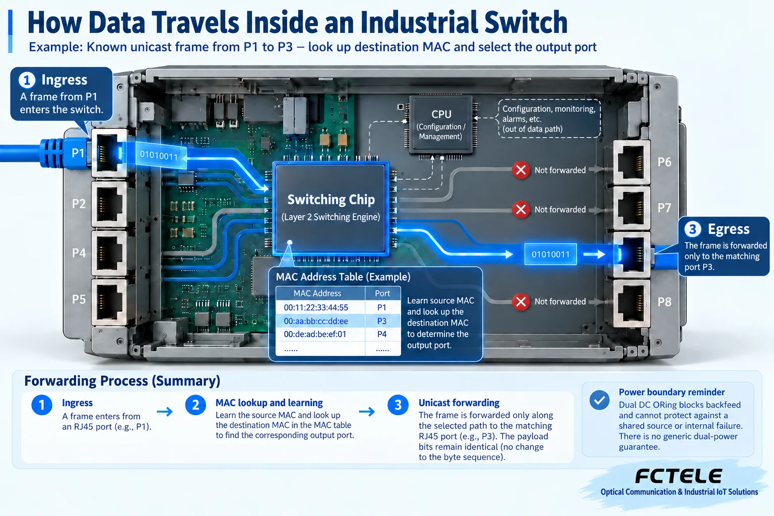
You can think of a switch as a sorter in a workshop. Devices put information into Ethernet frames, and the frames contain the MAC addresses of the sender and receiver. After receiving a frame, the switch learns which port the sender came from, then looks up which port the receiver should go out from. The MAC address table is this dynamically updated sorting record; it is not a contact list that an administrator manually fills in for every cable.
A normal unicast frame whose destination is already known is usually sent only to the corresponding exit port; when the destination is unknown, it may be forwarded within the broadcast domain to other eligible ports. Broadcasts and some multicasts also have their own handling rules. Therefore, ‘the switch automatically sends data only where it is needed’ cannot be understood as meaning no traffic will ever spread. VLANs, multicast control, and port isolation have different roles and cannot replace each other just because their feature names sound similar.
2. Confirm hardware capabilities and management features separately
Unmanaged switches mainly provide basic forwarding; managed switches usually allow you to view status and configure policies, but the available features are still determined by the model, firmware, and licenses. A device having a metal case does not mean it can configure VLANs; having optical ports does not mean it supports optical modules of all speeds; having two power inputs does not mean the two power sources must be connected in parallel or can be connected to different voltages arbitrarily.
First take a photo of the nameplate, record the full model, hardware version, firmware version, and port markings, then find the corresponding manual. Write the input voltage, power consumption, environmental requirements, and management method from the documentation into the device ledger. The ‘three power supplies,’ unified wide temperature range, and fixed DIP switch functions mentioned in old articles cannot be applied to all industrial switches. Especially for DIP switches, the same position may represent port isolation, ring networking, power supply, or other modes on different models, so do not flip them based on experience.
3. Establish an explainable baseline before first use
Do not immediately connect a new device to the entire production network. First, in an approved independent test environment, check the power and grounding, and connect only one test computer and one service terminal. Check the power status, port negotiated speed, and link status, then verify the actual service. For example, a camera should verify continuous images and recording, and a data acquisition device should verify platform readings, rather than accepting it just because an indicator light is on or a single Ping succeeds.
If the service requires IP communication, also confirm the terminal’s address, mask, gateway, and service settings. A Layer 2 switch can forward frames, but that does not mean it automatically assigns addresses or fixes incorrect addresses. The management address is the entrance for administrators to access the switch, and it is not the same as all service data being forwarded through this address. Devices with Layer 3 functions are a different matter, but they still need to be verified according to the actual configuration.
The baseline record should at least include: wiring diagram, port-to-terminal mapping, service test method, test duration, error counts, and status under normal load. When a fault occurs later, compare with this record first; it is usually more effective at narrowing down the scope than repeated restarts. When replacing cables, modules, or modifying configurations, change only one item at a time and keep the before-and-after results to avoid mixing multiple changes together.
4. What kind of fault does dual power supply solve?
Models that support redundant power can continue to be powered by another branch when one input branch fails. Internally, structures such as isolated selection circuits may be used; the specific behavior should be based on the product documentation. This capability does not mean the power of two power supplies is automatically added together, nor does it guarantee that any internal fault in the switch can be bypassed. ‘Having dual inputs’ cannot be understood as never stopping.
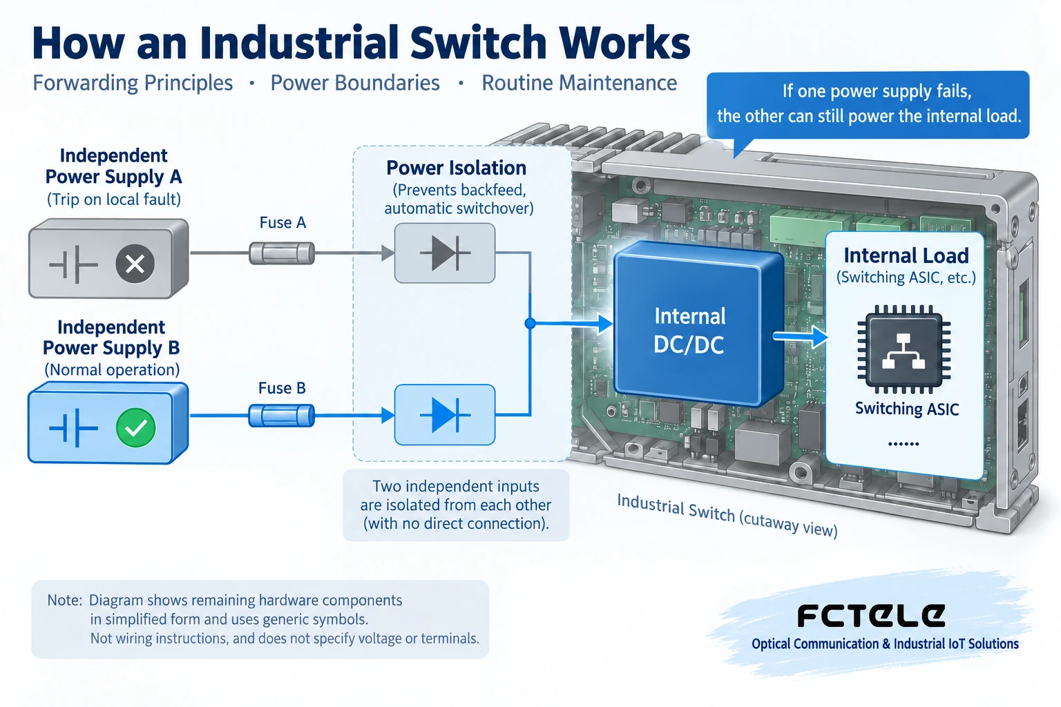
If both power supplies are plugged into the same socket that is prone to power loss, both branches will fail together when the socket loses power, which is a common failure point. Whether independent circuits, backup power, and how to test power-loss switching are needed should be decided by the on-site electrical plan. Work involving power distribution and live operations should be handed to qualified personnel; maintenance personnel should not casually unplug power from production equipment just to ‘try out redundancy.’
5. PoE and ring networking cannot be judged by a single checkbox
PoE involves both single-port capability and the overall power budget and power supply capacity of the entire device. Several cameras may have low power consumption normally, but after infrared lights start at night, the load may increase simultaneously; acceptance should consider this service state, not just the value at startup. Ports that do not support standard PoE cannot supply power to powered devices just because a network cable is plugged in, and wiring must not be altered to send power to ordinary data ports without authorization.
Ring networking is network path protection, not simply connecting several switches into a loop. An ordinary Layer 2 loop may cause frames to circulate repeatedly and generate a broadcast storm. When using STP, RSTP, or vendor protocols, it is necessary to confirm device compatibility, roles, and configuration, and to verify service recovery after a link interruption under approved test conditions. Power redundancy and network redundancy solve different problems, and neither can replace on-site acceptance.
6. Daily maintenance focuses on changes, not just ‘online’ status
Maintenance can start with four questions: Is there any abnormality in power supply? Do ports frequently go up and down? Are error or discard counters continuously increasing? Does the service slow down at specific times? Temperature should also be judged in combination with the cabinet environment and device specifications. A warm case may be normal heat dissipation, and insufficient cooling air may also cause the chip temperature to be too high; you cannot conclude whether the device is good or bad just by touching it.
Managed switches can view logs and port statistics when permissions allow; unmanaged switches do not have the same observation capability and require terminal records or test equipment. When a problem is found, save the evidence first, then arrange downtime for inspection. Back up configurations and record the recovery method. Firmware updates should verify the applicable model, version notes, and rollback conditions; do not treat updates as the first step for all faults.
7. How to avoid over-promising when using Feichang Technology products
The Feichang Technology official website’s rail-mounted managed product with 4 gigabit electrical ports and 2 gigabit optical ports lists selection information such as STP/RSTP, management, and dual power supply, while PoE involves optional configuration and power supply conditions. It can serve as a specific example for checking functions, but you cannot infer from it that all Feichang Technology models have the same capabilities, nor can you replace the customer’s on-site power, optical path, and service verification with the ideal feature descriptions on the page.
Before use, turn requirements into verifiable questions: How many service ports are needed, which type of optical port, whether PoE is required, how to manage, and how long recovery is allowed after a link break. Giving these conditions to Feichang Technology technical personnel to check the specific version is more likely to result in suitable equipment than a general request for ‘industrial grade, all supported.’ The ultimate goal of correct use is to give every function a clear purpose, keep a record of every maintenance action, and make every acceptance conclusion reviewable.
Translated from the Chinese technical article. Source first published: 2019-09-02. Source last revised: 2026-10-13T20:37:04+08:00. Read the Chinese source
