


If an industrial switch does not light up, occasionally loses power, or repeatedly restarts, first check the complete chain from the power source to the device terminals, then decide whether repair is needed. The power light only provides a local clue and cannot prove that all internal voltages are normal. Troubleshooting should start with safe, observable external conditions. Do not let on-site personnel open the enclosure to measure with power on or replace chips based on experience.
1. First distinguish between power supply and service problems
No indication at all, and the power light being on but the management page not opening, are two different types of symptoms. The former may involve external power supply, connections, protection, or internal faults; the latter may also be a management address, configuration, or network connection problem. Record the status and change pattern of the power light, run light, and port lights, then compare with the manual for that model. Different models have different light colors and flashing meanings. There is no unified conclusion that “green means everything is normal.”
First ask when the fault appeared: was it the first power-up after new installation, after adding cameras, when a motor started, or after a thunderstorm or maintenance? This timing relationship helps suggest a direction for checking, but it is not direct evidence. For example, if a restart happens at the same time as a motor starts, it may involve voltage drop or interference, but the power supply records still need to be verified; you cannot conclude that the device was struck by lightning just because of coincidence.
2. How does electrical power enter the switch?
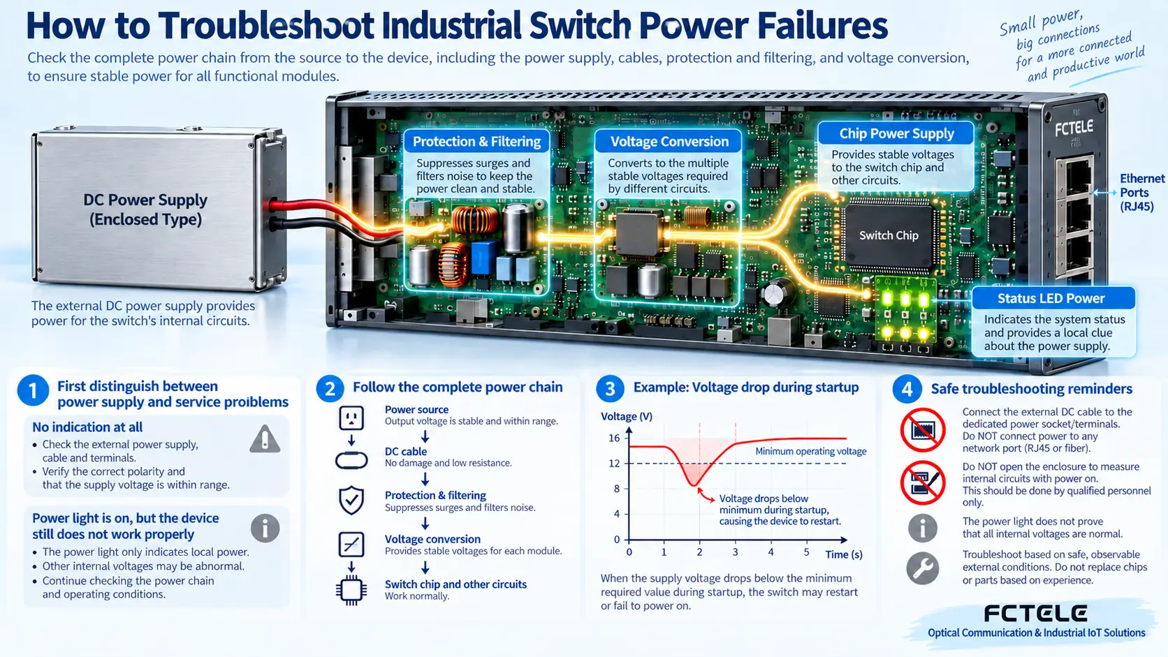
Many DIN-rail products use an external DC power supply, and there are also versions with built-in AC power supplies. After electrical power enters the device through the interface, it may pass through protection, filtering, and voltage regulation circuits, and then be distributed to the switch chip, processor, optical modules, and other parts. The role of the voltage regulation circuit is to convert an input within the allowed range into the voltage needed by the components. It does not mean the input can be arbitrarily high or low.
Indicator lights may be connected to a certain power node. The light being on only means that this part meets the conditions to light up. Another power branch, reset circuit, or startup program may still have problems. Conversely, the light itself or its control may also fail, so a light being off also cannot by itself locate an internal component. The internal structure in the diagram is used to explain the power supply relationship. It is not a real circuit diagram of a Feichang Technology model.
3. Before starting measurements, make the safety boundaries clear
If there is a burning smell, smoke, abnormal high temperature, charring, water ingress, or repeated operation of a protection device, stop repeatedly powering on. Isolate the device according to on-site procedures and contact qualified personnel. Checks involving mains electricity, distribution cabinets, and surge protection should be performed by qualified electrical personnel. Ordinary users should not open the power supply or switch, and should not bypass fuses, grounding, or protection devices to test the device.
External checks also need to distinguish between de-energized and energized operations. Loose connectors, damaged cables, and terminal assembly should be handled after de-energizing according to procedures and confirming safety. If voltage needs to be recorded, use instruments suitable for the on-site level, the correct voltage range, and protected measurement points, and have it done by capable personnel; do not directly connect the current range across the two ends of the power supply, as this is equivalent to creating a short-circuit risk.
4. If the power supply nameplate is normal, why is it still insufficient at the device end?
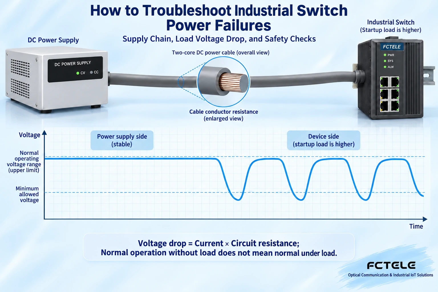
The nominal output of the power supply is a starting point, not proof of the voltage actually received by the device. Cables and connectors have resistance, and when current flows through them, a voltage drop occurs. The simple relationship is that voltage drop equals current multiplied by loop resistance; in practice it is also affected by connector condition, temperature, and power supply dynamics. Long thin wires, poor contact, or a shared power branch may cause the power supply end to be normal while the device end voltage is low.
Assume the loop resistance is one ohm and the current increases to two amperes; there will be about a two-volt drop on the line. This is only an example to explain the relationship, not a recommended wire gauge or device power consumption. If the device end therefore crosses below the allowed input lower limit, the internal parts may not be able to maintain operation. If it measures normal at no load but has problems after connecting the device or starting the load, you need to compare the loaded state rather than continue trusting the no-load reading.
The instantaneous demand at startup may also cause the power source to enter current limiting or protection. After the device loses power, the load decreases, the voltage recovers, and then it starts again. This can appear as periodic light on, light off, and port disconnection. Another possibility is that an internal fault in the device triggers protection. Not all cyclic restarts can be blamed on power supply capacity. After the external power supply evidence is normal, it should be handed to the manufacturer for further judgment.
5. Dual power and PoE also have boundaries
Dual power inputs are usually used for redundancy, but the specific switching method and input limits depend on the model. Two sets of terminals do not mean that two power supplies can be arbitrarily connected in series, nor that the total output capacity is doubled. If both paths come from the same upstream branch that can lose power, they may also fail at the same time. Independence needs to be considered together with the power system design, not just by looking at how many wires are connected.
PoE supplies power to terminals through compatible Ethernet connections. The switch itself being able to start does not mean it has the budget to power all cameras; a model supporting optional PoE also does not mean all shipped versions have this function. Input requirements, overall budget, single-port capability, and terminal compatibility need to be checked separately. Do not treat an ordinary network port as an arbitrary DC output port.
The mini four-electrical two-optical managed product on the Feichang Technology official website lists options such as dual DC input and built-in AC, as well as optional PoE conditions. When selecting, provide the complete model and check the actual nameplate, interfaces, and latest manual. Different options on the webpage cannot be mixed into one wiring rule. This article does not recommend applying one of the input ranges to other devices, nor does it promise continued operation under any surge based on promotional wording.
6. In what order should the fault range be narrowed down?
First save the model, power supply method, wiring photos, and fault time, and check whether the external power supply is interrupted and whether the protection device has operated. Then have qualified personnel confirm the terminal connections, polarity or the wiring method allowed by the model, and the device-end voltage. In a safely isolated test environment, a baseline can be established using a parameter-matched and known-good power supply and the minimum necessary peripherals. Do not directly swap unknown power supplies in a production cabinet.
If it recovers after reducing peripherals, check the PoE load, module power consumption, and shared branch separately. Do not directly take recovery as a conclusion that the switch has no fault. If it is still abnormal under the same conditions, record the symptoms after each action and stop repeated trial and error. Terminal voltage, light status, temperature, and service logs together form evidence. A single indicator is not enough to explain all internal conditions.
After repair or replacement, re-verify continuous operation, startup, and power switching using the actual planned load. Record the environment, connections, and test duration. Do not “test” industrial-grade capability through artificial short circuits, connecting bare wires, or heating to unknown temperatures. What the manufacturer usually needs is a complete symptom description and external inspection records, not a self-guessed list of damaged chips.
The fault ratios, specific chip cold-solder frequencies, and unified motherboard voltages in the old article have no reliable statistics or model basis, so they are not continued in this article. Parts requiring internal inspection are left to authorized repair. Users can start from the power supply chain, load, and on-site evidence to describe the problem clearly and safely.
References:Feichang Technology industrial switch categories;Power supply versions and optional condition details. Specific repair, power supply, and protection plans are subject to the model manual and the judgment of qualified electrical personnel.
Translated from the Chinese technical article. Source first published: 2019-08-21. Source last revised: 2026-10-13T20:37:04+08:00. Read the Chinese source
