


Optical module stability cannot be proven by just one light-up or one optical power screenshot. Optical alignment, assembly retention, electrical connections, temperature, and host compatibility can all affect continuous communication. For manufacturers, verify whether assembly variations change optical and electrical performance; for field users, request test evidence for the corresponding model and check the complete link, and do not open the module to adjust lenses or solder structures.
1. Stability first requires clarity on what is being measured
“Stable” can mean small changes in optical output, or it can mean the host continuously recognizes the module, there are few service errors, or it still meets requirements after specified environmental exposure. These are not the same metric. Before purchasing or testing, specify the object, rate, host combination, load, temperature conditions, observation time, and pass/fail method; otherwise, two reports both saying “test passed” may not be comparable at all.
The module handles electrical-to-optical and optical-to-electrical conversion under specified conditions, the host handles the corresponding interface and service processing, and the fiber handles propagation. A system fault may come from any of these parts. Module temperature, transmit power, receive power, and error statistics are different pieces of evidence and must be understood together with time and test conditions; a change in one value cannot be directly interpreted as an internal assembly failure.
2. Why optical alignment changes coupling
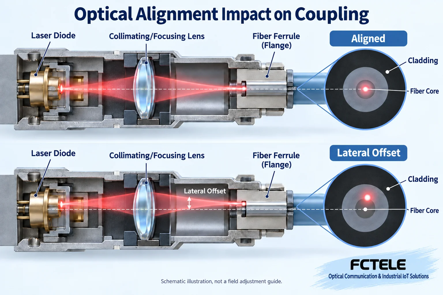
In structures that use lenses to couple to the fiber core, the light source, lens, and effective receiving area need to maintain proper positions. Coupling is the process that lets light from one end effectively enter the propagation structure at the other end. Changes in lateral position, angle, or axial distance may reduce effective coupling; the light source may still emit light, but less light enters the required path.
Figure 1 uses alignment and lateral offset to explain this relationship. Different types of modules may use different optical structures and packaging methods; the dimensions or positions in the figure must not be treated as actual assembly tolerances. Alignment is also not a conclusion that a single “coaxial inspection pin” can prove; mechanical positioning checks and optical performance measurements should work together according to design requirements. Thorlabs’ fiber coupling material explains the importance of aligning the beam path with the fiber axis. Here, only the general optical relationship is cited, and its experimental adjustment steps are not used for field module repair.
3. Assembly retention must withstand subsequent condition changes
Adjusting a component to the right position on a prototype only confirms the state at one point in time. The fixing structure, materials, connections, and process need to keep performance under specified transport, installation, and operating conditions. Adhesive bonding, welding, and mechanical positioning methods each have their own design conditions; one cannot simply assume that changing to a different adhesive or improving the precision of one fixture will solve all stability problems.
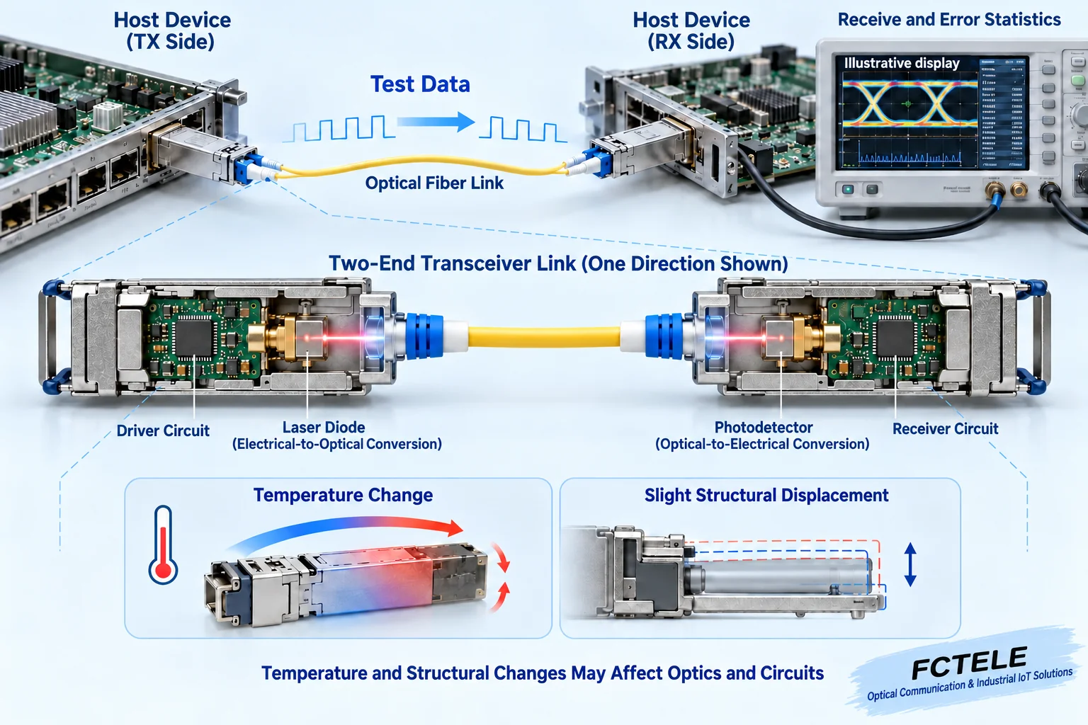
When temperature changes, the dimensions of different materials and device characteristics may change; mechanical loads may also affect positioning or contact. Optical shift is only one possible mechanism; the laser driver, receiver circuit, and power supply also have operating boundaries. Changes need to be measured under repeatable conditions before determining the cause, and long-term reliability cannot be inferred just because the housing looks solid.
Improvements in manufacturing should record the design version, process conditions, samples, and measurement methods, and compare corresponding results before and after the improvement. Without an actual report, one cannot claim that Feichang Technology completed a certain fixture upgrade, improved coaxiality, or increased mass-production yield. This article explains how to raise and verify questions; it does not invent production processes or achievements for any company.
4. Optical measurements and service measurements must be separated
Optical power measurement answers how much light is received at a specified test point, while service testing answers whether the signal is correctly received and processed. Even if receive power is normal, errors may still occur due to encoding, host compatibility, timing, or waveform conditions; short-term normal service also does not mean optical margin is sufficient under all temperatures and loads. The two types of tests should form a complete record rather than replace each other.
Test data can be generated by applicable instruments or device interfaces, and the receiving end counts errors or service results in an agreed manner. Instrument capabilities, sampling conditions, and statistical definitions must be clear. An eye diagram shows one relationship between signal amplitude and timing; one cannot declare zero errors just because the pattern looks good. Error count, error ratio, and newly added errors during the observation period are also not the same quantity.
5. Tests must be reproducible
First fix the host and software version, module model, peer end, fiber, and service conditions to establish a normal baseline. Then apply the conditions that need verification according to the model specification or project plan, and record identification, link, power, and service performance during the changes. Temperature range, hold time, number of cycles, and mechanical conditions should all come from explicit requirements; do not set a uniform standard for all modules on your own.
Measuring instruments also need applicable ranges and status records. When an experiment fails, first confirm the test configuration, optical connector cleanliness, and host support; do not immediately attribute the problem to the module under test. If the module, fiber, and software are all changed at the same time, even if recovery occurs, it is impossible to clearly determine which condition changed the result. Comparisons should change only one factor as much as possible.
The number of samples and test coverage determine where the conclusion can be applied. One prototype working in one test does not prove permanent compatibility for the entire batch, all firmware, or all hosts. Not observing errors can only describe the recorded conditions and period; it cannot be rewritten as meaning there is no possibility of any fault. Reliability metrics and warranty commitments should also be checked separately, and an average statistical value should not be treated as a guarantee of the service life of a single module.
6. Field users should not replace troubleshooting with internal adjustment
The more common field-checkable items are host compatibility, endface contamination, latches, jumper stress, power supply, and heat dissipation. By comparing logs, diagnostic trends, and known-good spare parts, the problem scope can be narrowed. An abnormality when temperature rises may be related to the module, but it may also be related to cabinet heat or host status; record the corresponding relationship before verifying.
Do not open the module to turn optical components, re-glue, or re-solder internal solder joints. This may damage protection, change alignment, and affect the warranty, and it may not solve the real cause. If visible damage, abnormal odor, or water ingress is found, stop trial use according to safety procedures and contact service personnel. Follow ESD and optical safety requirements during handling, and do not look directly at an optical interface with light.
7. Feichang Technology hosts and modules should be verified as a combination
Feichang Technology Network-managed DIN-rail industrial switch category includes four electrical and two optical products listing configurations such as SFP optical ports, fanless structure, and redundant power supply. Pluggable optical ports make it easy to select modules according to the line, but the host’s environmental description cannot automatically serve as environmental evidence for any third-party module.
During procurement, require the supplier to specify the host version, module configuration, installation conditions, and applicable test records. Fanless does not mean no heat dissipation space is needed, and dual power supply also requires checking the upstream sources. Only when the actual combination passes service verification under the required conditions do these structural features truly serve continuous field communication, rather than remaining a few reliability slogans.
Source note: The above optical material only verifies the general coupling mechanism, and the Feichang Technology material is used for the corresponding host structure. The two figures are general principle illustrations, not factory photos, measured results, or internal assembly guidance.
Translated from the Chinese technical article. Source first published: 2020-12-28. Source last revised: 2026-10-13T10:45:04+08:00. Read the Chinese source
