


Start with the conclusion
First ask where the “dual” is: interfaces, lines, or a complete system
When a device is described as having a dual bus or dual path, the first thing to confirm is whether this means two copper ports, two independent DP services, two optical directions, or two control systems. They may all look like they have two lines, but their actual tasks and fault coverage differ, so you cannot directly assume from the word “dual” that the master, slaves, power supplies and links are all redundant.
A procurement requirement should draw the master, slaves, copper segments and optical segments, and mark whether each item is an extension of the same service or an independent system. List the faults you want to handle: one optical cable section, device power loss, or controller failure, then check which type the model supports. This is more practically meaningful than just comparing the number of optical ports.
Two electrical ports may only segment the same logical network
A repeater or isolation device can use two electrical ports to connect two copper network segments. Electrically, each has its own receive, drive and reference conditions, but logically they may still belong to the same DP communication domain. It does not automatically create a second independent master system just because it has an extra interface, nor does it mean all parameters on both sides can differ freely.
Each segment needs its node load, termination, power supply and wiring checked separately. How the device specifically forwards data and whether it has independent channels depends on the manual. Port electrical isolation solves part of the conductive relationship, while independent services, protocol routing and controller redundancy are another layer. These functions cannot substitute for each other.
Two optical ports usually correspond to optical directions, and their use is determined by the mode
Two optical paths can be used for uplink/downlink chain extension, path backup, or a supported ring network structure. Inside a corresponding optical path there may also be transmit and receive directions, so you cannot directly count two fiber cores as two independent networks. Single-fiber bidirectional and dual-fiber transmit/receive also have their own optical conditions. Port count, fiber core count and service channel count should be described separately.
The public details of Feichang Technology FC2P-P1G list one DP service and two optical interfaces, as well as chain, star and redundant ring network uses, making it suitable for checking DP optical topology tasks. It cannot serve as evidence that this model carries two independent DP buses. The actual ordering version, mode and compatible devices need to be confirmed, and functions cannot be inferred from the dual-bus title of an old article.
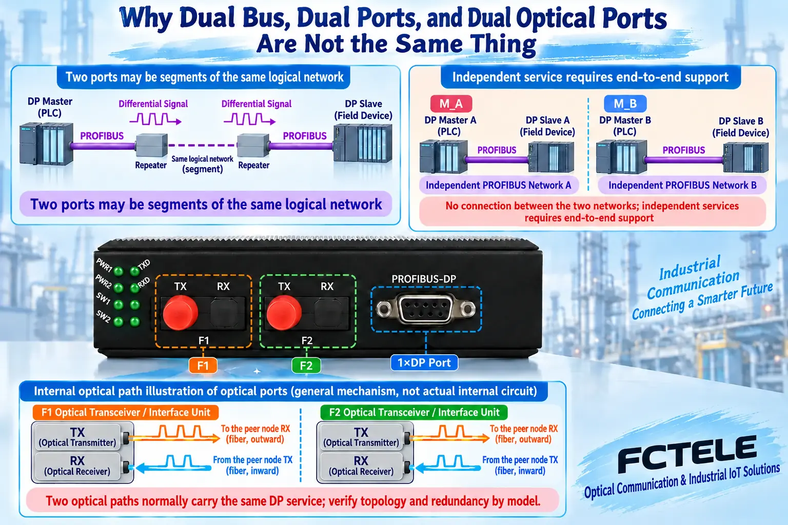
Two independent services require end-to-end support
If the task really is for DP network A and network B to transmit independently, the channels, master configuration, slave interfaces and remote recovery must all be clear. A device having two interfaces does not prove it can independently multiplex two communication domains over the same optical path. Before connecting, there should be a corresponding function and mapping description.
If the goal is control system redundancy, it also involves the controller, application, terminals and switching coordination, and cannot be completed simply by replacing a two-optical-port repeater. The redundancy rules of different systems should not be mixed. The two networks in common teaching diagrams only explain an independent relationship and do not imply that any Feichang Technology model already supports that combination.
A redundant optical path must be able to detect faults and handle forwarding
Closing a ring only shows that the physical lines form a loop. The device still needs a compatible detection and forwarding mechanism to avoid inappropriate repeated propagation and to use the remaining path when a fault occurs. Settings and implementations may differ between manufacturers. A PROFIBUS optical ring cannot directly copy Ethernet blocking ports, STP, or parameters from other buses.
The design must also consider propagation and repeater time and the DP service waiting conditions, and cannot rely only on a ring recovery indicator. Laying two lines in the same vulnerable conduit, or taking two power ports from the same faulty power source, also creates a common failure point. Redundancy is not a synonym for the number of interfaces; the actual fault scope should be reflected in the topology and installation.
For one broken fiber, first check whether a complete usable path still exists
Assume three nodes form a redundant optical ring: N0 is the master access point, N1 is the target slave access point, and N2 is on the other side. If the optical path between N0 and N1 is broken, and the device mechanism allows it, a query can go from N0 to N2 and then to N1, and the response returns along the corresponding reverse path. This is only a single-fault logic example, not a fixed routing algorithm for a specific device.
The broken section should no longer be drawn as able to carry service. If a node itself loses power, the local device may go offline with it; multiple broken fibers may also form an isolated island. These situations differ from a single broken cable. The remaining path in the example cannot be expanded to mean that service never breaks under any fault, and a fixed recovery time must not be written without basis.
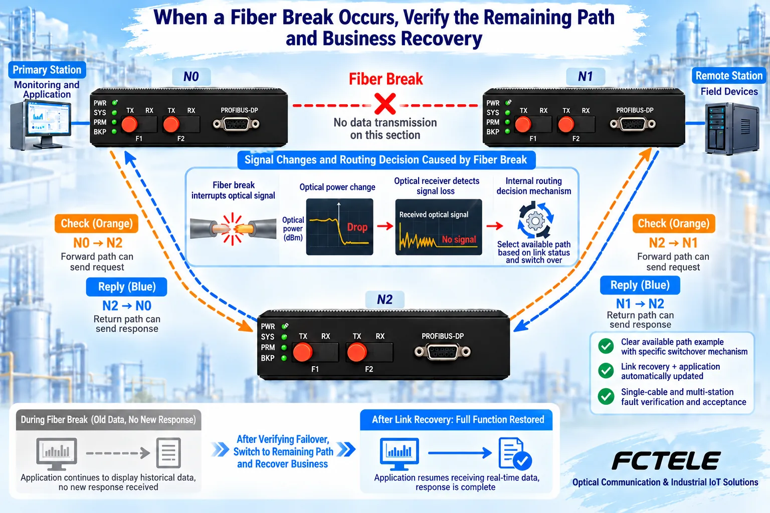
Optical-side pairing, copper-side termination and power supply still need to be met item by item
The fiber type, wavelength, single-fiber or dual-fiber mode, interface end face and loss of each optical link need to be checked; versions cannot be mixed within the same ring just by connector appearance. Copper network segments still need correct handling of reference and termination, and you cannot arbitrarily lengthen branches or repeatedly enable termination just because there is a redundant optical path.
The power supply, environmental and alarm functions declared for a product belong only to the corresponding delivery configuration. If web page statements are inconsistent, ask the supplier to clarify. Port isolation, surge protection, fiber non-conductivity and protection of the complete system are different conditions, and one specification cannot be generalized to all fault scenarios.
Acceptance distinguishes link recovery, DP recovery and new data
First record the communication cycle, diagnostics and actual data under the normal topology, then within an allowed window create one specified link interruption and observe alarms, remaining connectivity and complete DP exchange. After restoring the original line, also check the behavior of returning to the normal state; you cannot test only disconnection and not recovery.
The application should distinguish the last valid data from newly exchanged data. A link light turning back on does not mean the values have been updated. Record the recovery process, service timeout and target load to judge whether project needs are met; acceptance of reading and acceptance of action control are separate, and reconnection cannot prove that control execution is correct.
Delivery documents should state which faults are covered, not a vague self-healing claim
The documentation should retain master/slave roles, copper and optical paths, mode, configuration version, power supply and common points of the paths; the test table should separately record single optical path, node power loss and other authorized faults, and one successful result should not replace all of them. Interface photos are only for appearance checking; logical wiring is not a pin construction drawing.
Dual electrical ports are used for segmentation, dual optical directions are used to adapt to the topology, and independent services and system redundancy require additional basis. Once these layers are explained clearly, and the actual service behavior under the target fault is then proven, the customer can judge where the selected solution is practical and which problems still need other measures.
Data note: The illustrations are general mechanism diagrams and have been technically checked; the appearance of the marked model refers to the official website photo, and the other cutaway views and components do not represent the internal circuit of an actual Feichang Technology product. They are not measured waveforms or real project sites. Wiring and power supply are subject to the delivery manual.
Verification materials:Feichang Technology FC2P-P1G ring-type DP optical transceiver 1171
Feichang Technology Profibus-DP optical transceiver categories
PI PROFIBUS Design Guide
PI PROFIBUS termination and connection instructions
FOA optical link loss budget
Translated from the Chinese technical article. Source first published: 2021-06-09. Source last revised: 2026-10-13T10:45:04+08:00. Read the Chinese source
