


An RS232 to RS485 converter changes the electrical interface so that devices using different serial port voltage levels can exchange bytes. It usually does not change the device protocol, and it does not automatically assign addresses to instruments. Once you understand single-ended, differential, and half-duplex, you can see why you cannot simply mix the wiring, why long cables need proper wiring practices, and why “automatic send/receive” still has conditions.
The two interfaces observe signals in different ways
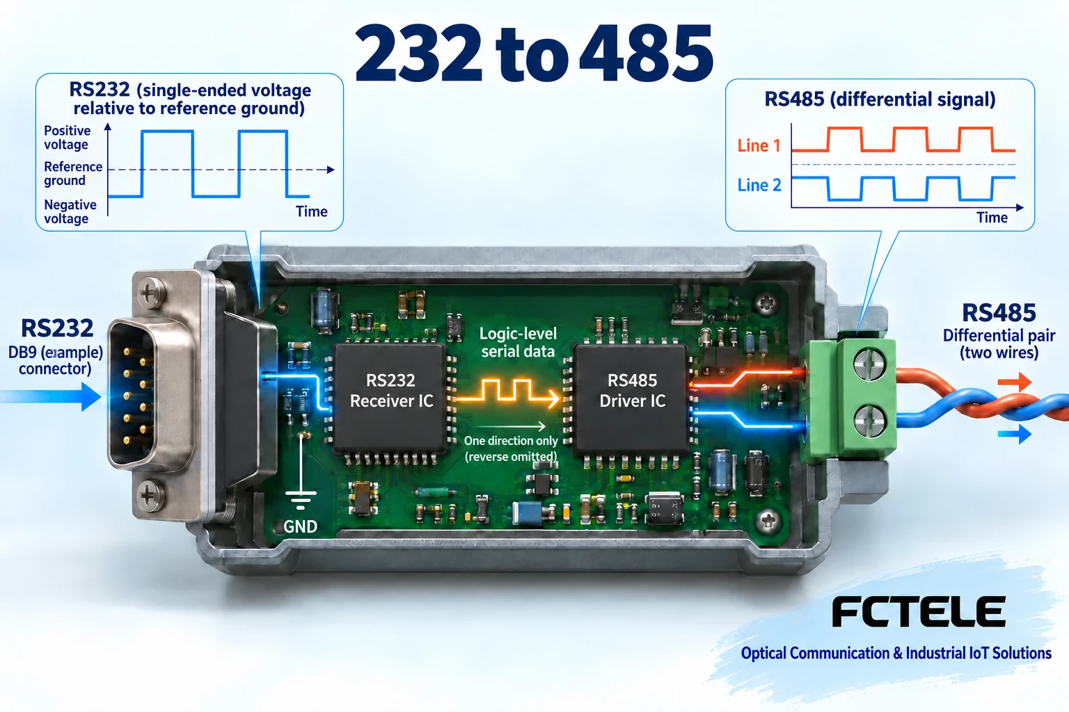
An RS232 receiver observes the signal voltage relative to a reference ground, which is called single-ended transmission; RS485 mainly observes the voltage difference between two signal lines, which is called differential transmission. When a differential line is affected by similar external interference, the receiver can suppress the part that changes in common, but it does not eliminate all noise or allow any arbitrary ground potential difference. You can think of it as comparing the height difference between two people rather than only looking at how tall one person stands; in practice it is also limited by the receiver’s common-mode range, the cable, and the protection design. This is also why different voltage-level standards cannot interoperate by simply changing plugs; the converter must include the corresponding receiver and driver circuits.
How one byte passes through the converter
The computer outputs the serial waveform from the RS232 transmit pin; the RS232 receiver circuit first restores it to an internal logic state, and then the RS485 driver generates the differential line signal. When the instrument responds, the RS485 receiver restores the signal in the opposite direction, and the RS232 transmit circuit outputs a voltage level the computer can recognize. The actual chip combination varies with device design; the diagram shows functional relationships and does not represent a specific circuit board structure. The byte format is usually still determined by the UART controllers at both ends, so baud rate, data bits, parity, and stop bits must be compatible. Correct voltage-level conversion also cannot make two different instrument protocols understand each other; checksums and addresses still need to be handled by the application.
Why half-duplex requires controlling who is sending
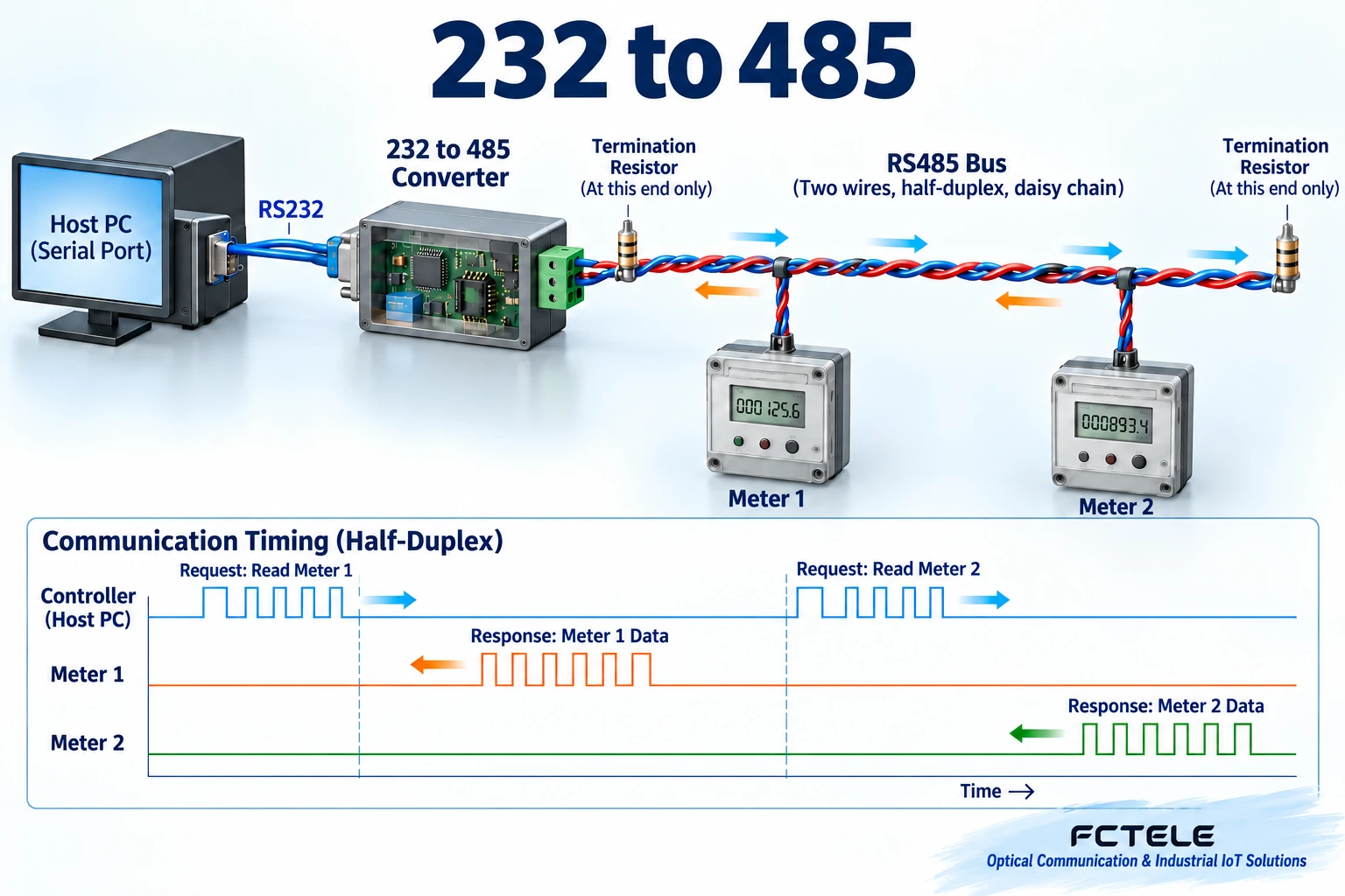
Common two-wire RS485 uses the same pair of wires to transmit in both directions, but usually multiple drivers cannot contend at the same time, which is called half-duplex. After the master sends a request, it needs to release the transmit state so that the polled slave can respond. The converter may use automatic direction control, or it may require a control signal, depending on the model. Automatic control must correctly determine when transmission starts and ends, and both switching and buffering have implementation conditions; “automatic” cannot be taken to mean “zero delay.” If release is too late, it may cover the beginning of the response; if too early, it may damage the end of the request. When troubleshooting, consider character timing, response time, and direction control together; do not just increase the serial port speed in an attempt to solve a bus conflict.
Do not wire the RS232 side based only on plug shape
DB9 is a common connector shape, but the device pin definitions, transmit/receive directions, and roles must be checked. The local transmit should enter the remote receive, and whether the reference ground and handshake lines need to be connected is decided according to the manual. USB-to-serial adapters may also have different electrical outputs, and TTL serial, RS232, and RS485 cannot be treated as the same thing. Serial-powered converters depend on the relevant signals and power supply design, and their applicable conditions differ from externally powered types; you should not assume that all computer ports can supply power stably. When there is a long-distance ground potential difference on site, isolation, protection, and grounding solutions must also be evaluated. Unknown pins must not be shorted at will, and the serial ground must never be used as a substitute for protective grounding.
What do RS485 wiring, termination, and biasing do?
The bus usually connects devices along one trunk, and branches should follow the design requirements as much as possible; it cannot be arbitrarily laid out in a star shape. Signals travel along the line and may reflect when they encounter an unmatched end; termination resistors are used to reduce this reflection. Whether they are needed, what value to use, and where to place them should be determined according to the cable, speed, distance, and device design; you cannot add termination to every instrument. Biasing is used to establish a determinable idle state when no one is driving, and it is not the same function as termination. Some receivers have fail-safe features, but this still must be checked against the system plan. Manufacturers may mark A, B, positive, and negative differently, so wiring must be based on the definitions, not on applying some fixed letter-to-voltage mnemonic.
Treat contradictions in the original parameters as a prompt to verify
The old text lists different temperature ranges, dimensions, and power-taking descriptions at the same time, and also has inconsistent speed unit notation; these cannot be pieced together into complete specifications for a particular model. This article does not make commitments based on them regarding transmission distance, node count, protection level, or operating temperature. How many devices a bus can connect involves the load of each receiver, biasing, and line conditions; distance and speed also constrain each other, and not every speed can reach one unified distance. When purchasing, request the manual for the corresponding version and check the input power, interface, isolation, direction control, and test conditions. A nominal electrostatic protection rating also does not mean all surges can be withstood, and it does not replace on-site protection design.
Use one instrument to verify a minimal system
Suppose a computer needs to read one RS485 instrument. First choose a converter with clear specifications, and check the parameters, wiring, and power supply on a short line. The software sends a read-only query allowed by the manual, and you observe whether a response with the correct address, length, and checksum is received. After confirming that a single unit works normally, gradually add lines and devices, and assign each slave a correct and non-conflicting address. Only the queried object should respond; other devices should not transmit unexpectedly. Some problems appear only with multiple nodes or long lines, so you need to record termination, biasing, and waveforms, rather than repeatedly treating a successful single-unit test as the whole project passing. The example is only a verification method and does not mean all instruments use the same protocol or address configuration steps.
What to check separately for garbled text, no response, and occasional dropped bytes
For garbled text, first check the voltage-level standard and character format; for no response, also check the target address, protocol command, direction switching, and device status; for occasional dropped bytes, check the power supply, reflection, interference, and software receive buffer. You can use suitable instruments to observe signals, but you must not use an incorrect grounding method that causes a short circuit through the oscilloscope ground clip. Save each change and result, and adjust only one variable at a time. Acceptance should cover multiple nodes, the real cable length, both transmission directions, and long-term polling. The value of a converter is to let compatible protocols cross the electrical interface boundary, not to make any serial device plug and play; once this boundary is clear, selection and troubleshooting become more reliable.
Principle verification sources:Official source 1;Official source 2. The general mechanisms and examples in the text do not replace the manual for the corresponding model.
Translated from the Chinese technical article. Source first published: 2019-11-05. Source last revised: 2026-10-13T13:19:24+08:00. Read the Chinese source
