


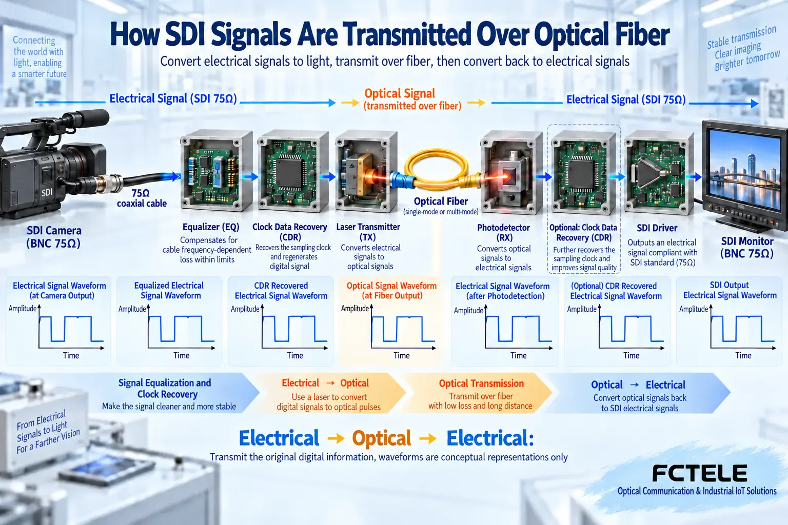
An SDI optical transceiver solves the problem of sending digital video over a long distance. The camera already outputs an SDI serial digital signal; the optical transceiver receives this signal, converts it into a form suitable for fiber transmission, and then restores it into an SDI electrical signal at the other end. It is usually not a video recorder, and it does not need to first compress the picture with H.264. The most effective way to understand it is to look segment by segment along the coaxial input, internal processing, fiber, and coaxial output.
1. First distinguish the interface from the information
SDI is a serial digital interface. Picture samples, timing information, and permitted auxiliary data are arranged as specified into a high-speed bitstream. Serial can be understood as information passing through one channel in sequence, but it is not video frames being sent one by one like ordinary files. BNC is only a common connector shape; analog composite video can also use BNC. Being able to plug in the connector does not mean two devices use the same signal. Connecting an SDI camera to an analog video optical transceiver will not become compatible just because the cable was changed.
SD-SDI, HD-SDI, 3G-SDI, and higher-speed grades each have their own electrical and data mapping requirements. The G in 3G means a transmission rate on the order of gigabits, not third generation, and not three pictures per second. The nominal rate of a common 3G grade is about 2.97 Gb/s. Whether a specific image can pass also depends on checking resolution, frame rate, scanning method, color sampling, and the corresponding mapping; you cannot check only the two words “high definition.”
2. How the transmit end receives the electrical signal
The longer the coaxial cable, the more obvious the loss in the high-frequency part often becomes, the pulse edges become slower, and the margin for the receiving circuit to judge zero and one becomes smaller. The input equalizer compensates for the frequency-related loss caused by the cable under permitted conditions, making the signal more suitable for subsequent decision-making. Its effect is similar to improving how legible handwriting is, but it cannot bring back data that has already been completely lost out of thin air. Connectors, cable impedance, and termination matching are still important.
A design with a retiming function also extracts the clock from the received bitstream, judges the data at the appropriate moment, and then outputs according to the recovered rhythm. Different models may arrange clock recovery in different positions, and may also support bypass or multiple rates; you cannot infer from one general block diagram that all products use the same chip. Both equalization and retiming are premised on the input signal still being within the permitted range. When lock is lost, a “stronger algorithm” cannot guarantee a normal picture.
3. Electrical-to-optical conversion is not re-shooting the picture
The subsequent circuit drives the optical transmitter module and sends the data carried by the electrical signal into the fiber. The photodetector at the receiving end converts the received light into an electrical signal, and after necessary reception, clock processing, and line driving, sends it from the SDI output interface to a monitor or recording device. The core task here is to transmit existing digital information, not to increase the camera’s resolution, and not to automatically turn SDI into HDMI or network video.
Some devices multiplex multiple video channels or other services onto one optical path. Multiplexing means the transmit end arranges the information of each channel according to the design, and the receive end must understand the corresponding organization method in order to restore it. Both devices saying “optical port” or both using the same wavelength is not enough to prove that they can be paired. Single-channel transparent transmission, dedicated multi-channel multiplexing, and Ethernet optical modules are different objects; replacing one with an ordinary network SFP does not necessarily replace a video optical module.
4. Why distance cannot be judged by only one kilometer number
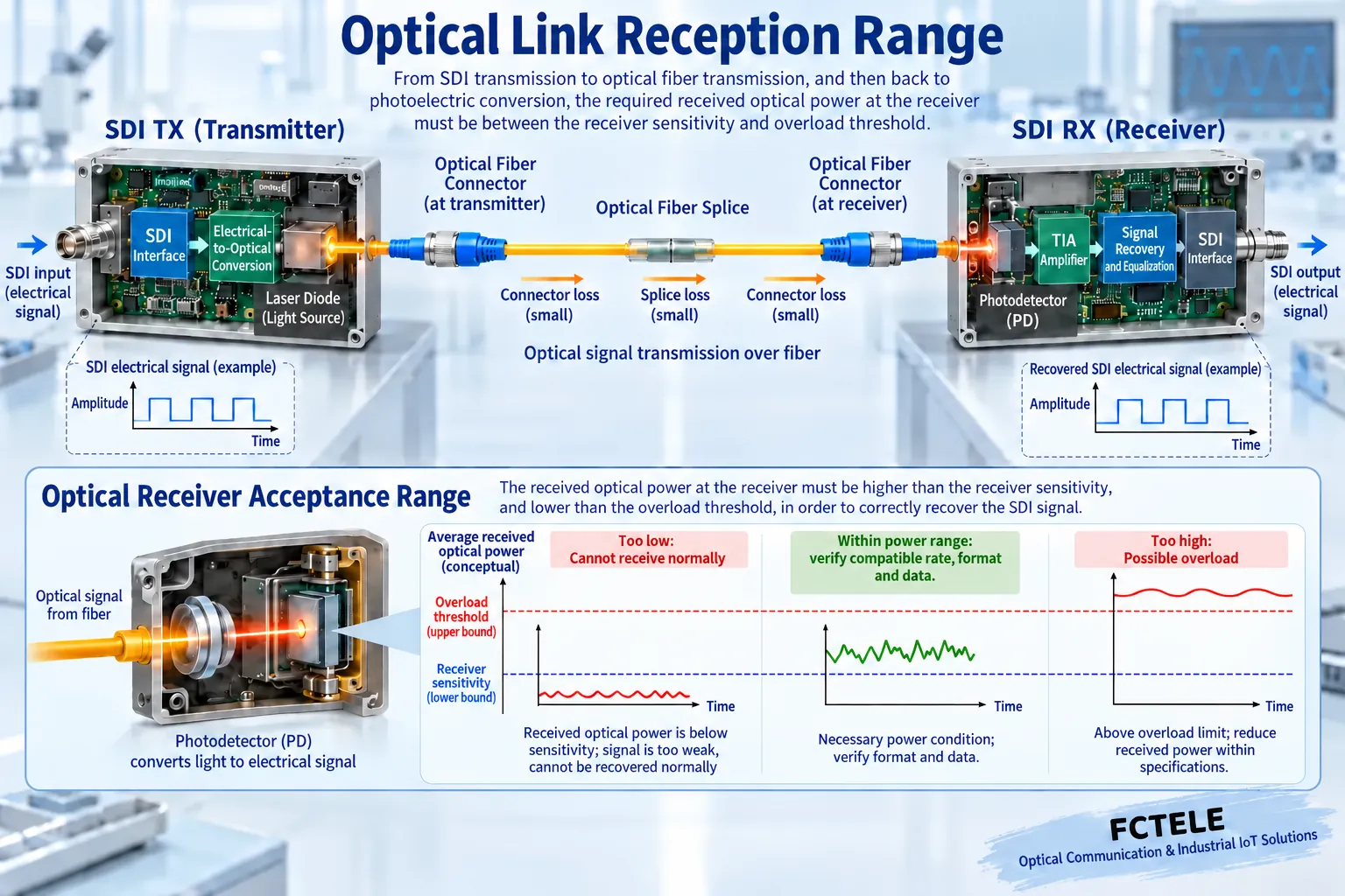
Fiber is not lossless. Transmit power, fiber attenuation, connector loss, and splice loss together determine how much light the receiving end can receive. If received power is too low, decision-making is affected; if it exceeds the permitted upper limit, overload may also occur. Therefore, long-distance models used over short distances also need their receiving range checked. Engineering calculations should use the transmit power, receive sensitivity, overload point, and necessary margin given by the ordered version, and should not directly treat the advertised maximum distance as an on-site guarantee.
The choice of single-mode or multimode, single-fiber or dual-fiber, connector type, and wavelength must correspond item by item between both ends and the on-site fiber. Single-fiber bidirectional devices also need complementary transmit and receive configurations. Do not look directly at the optical interface or use your eyes to judge whether light is coming out; end-face inspection and power measurement should use suitable tools. Insertion, removal, and cleaning should follow the device and tool instructions; confirm the direction before measuring, to avoid treating an output port as an input port.
5. Apply the Principles to Model Selection
The Feichang Technology website’s single-channel 3G product information provides SD, HD, and 3G grades, and lists the video interfaces of the transmitting and receiving devices and different fiber configurations. It is suitable for checking how one SDI link is extended, but it cannot be used to conclude that the entire SDI series supports 12G. The website also has separate single-channel 12G product information; when purchasing, you should provide the actual video mode and optical path conditions so that the supplied configuration corresponds item by item to the requirement, rather than only saying “buy a pair of HD optical transceivers.”
For example, if the camera outputs 1080p60, first confirm its actual SDI mapping, then confirm that the transmit end, receive end, and monitor all accept this format. If the monitor has only HDMI input, an active converter is also needed; this is not a function that an optical receiver automatically has. When audio, control, Ethernet, or telephone channels are needed, the number of interfaces, direction, and format should also be confirmed separately; optional functions on one product page cannot be transferred to all single-channel devices.
6. How to prove that transmission is actually normal
First use a short qualified coaxial cable to establish a baseline on a desktop between the source, the paired optical transceivers, and the receiving device, and record the format and light status. After the baseline is normal, replace the on-site coaxial section and optical path, changing only one condition at a time. The power light being on only indicates part of the power supply status, and the optical link light being on also cannot by itself prove that all video data is correct; ultimately you must verify the picture, sound, and errors and loss of lock during continuous operation.
If there is occasional black screen, check segment by segment according to power supply, input coaxial, optical reception, output coaxial, and terminal compatibility. Do not replace all components immediately, and do not arbitrarily adjust laser power or force a firmware upgrade without confirming the model. Keeping the time, format, cable, power, and replacement results can help distinguish insufficient link margin from unsupported format. The latency of transmission equipment should also be verified according to the actual system; digital transmission does not automatically mean absolutely zero latency.
For multi-channel transmission projects, the correspondence between input and output should also be checked channel by channel, to avoid port numbering or pairing configuration errors. During acceptance, let each channel’s source have a recognizable test picture, not just check one of the channels; for devices with routing or multiplexing settings, record the configuration according to the instructions. In this way, when a terminal is later replaced, it can be confirmed which channel the abnormality occurred on, rather than only saying that the whole fiber has a problem.
Sources:SMPTE standards index;TI LMH0346 retimer information;Feichang Technology single-channel 3G SDI optical transceiver;Feichang Technology single-channel 12G SDI optical transceiver. The illustrations explain general mechanisms; they are not product physical objects, measured waveforms, or certification documents.
Related topics:How to understand SDI synchronization: the difference between bit clock, line and frame markers, and studio synchronization;SDI optical transceiver signal processing: what equalization, clock recovery, and retiming each solve;How to test and accept an SDI optical transceiver: format, errors, optical power, and continuous operation;How to evaluate SDI optical transceiver power consumption and temperature rise: power supply loss, heat dissipation, and operation arrangements;SDI optical transceiver installation and troubleshooting: short-cable baseline, optical-link commissioning, and segment-by-segment localization;How to choose between SDI surveillance and IP surveillance: transmission, recording, latency, and security boundaries;How to check no picture or no sound when converting SDI to HDMI: power supply, lock, and display compatibility
Translated from the Chinese technical article. Source first published: 2019-10-25. Source last revised: 2026-10-13T13:19:24+08:00. Read the Chinese source
