


When discrete contact signals fail to operate, first distinguish power, optical path and channel status lights by specific model, then check section by section along the input, transmission, output and receiving system. Contact-only equipment cannot apply video light, image snow or RS232 wiring rules; light names and on/off meanings need to be checked against the actual panel and delivery documents.
1. Record the Symptoms Before Replacing Equipment
Photograph both end panels and wiring, write down clearly the model version, power supply, channel direction, and whether the fault affects one channel or all channels. Confirm whether the fault occurs at power-on, during operation, during main/backup switching, or during continuous running. Record the configuration before changes, to avoid changing wiring while troubleshooting and finally not knowing which step produced an effect.
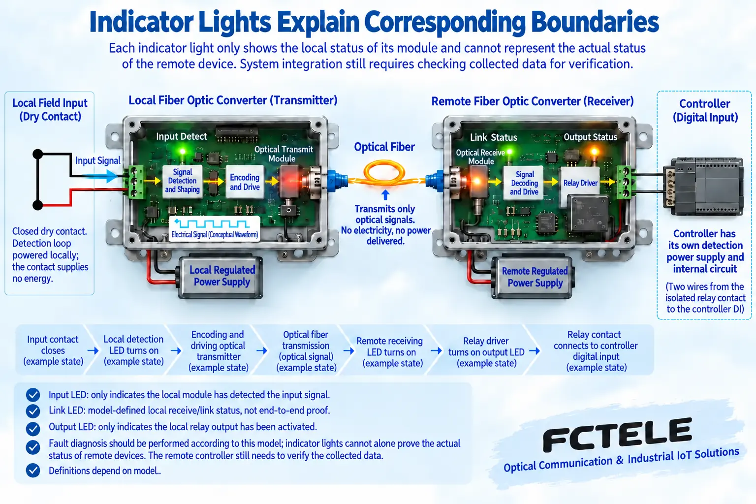
The power light usually helps determine whether the equipment is in a powered state, but the light being on does not prove all power parameters are qualified. The optical path light may indicate synchronization, reception, alarm or other states, and the meanings of on, off and flashing are not uniform. The channel light may also show input recognition or output status, and cannot directly prove that the external load has operated.
Feichang FCP-K16G public documentation provides per-channel open/close status indication and main/backup optical paths; FCP-K4 provides channel indication and loss-of-link output settings. Different products should not share one fixed light table. When the documentation does not give a precise definition of a certain light, record the actual state and verify it, and do not guess based on light color.
2. When neither end responds, check the power supply first
Check the actual power model, connection terminal and polarity, measure voltage according to rated conditions, and pay attention to whether it drops after loading. Adapter, plug or terminal contact problems may cause intermittent restart. Different product versions have different power conditions, and a fixed voltage cannot be copied from one model to another device.
If there is dual power, verify the wiring and power source separately, and do not randomly connect unknown power sources in parallel. Protective grounding and enclosure connection are handled according to the engineering plan. Inspections involving mains electricity, live work inside cabinets or fuse protection are carried out by personnel with the corresponding conditions; troubleshooting does not restore operation by short-circuiting protective devices.
3. Local channel light does not change with input
Start checking from the signal source: whether the mechanical contact really opens and closes, whether the powered sensor receives the specified power supply, and whether the output type is compatible with the input. Under safe shutdown conditions, a test contact or signal source permitted by the manual may be used to replace this section. Before testing, confirm the terminal definitions, and do not short-circuit on an unknown voltage loop.
Verify the common terminal, polarity, input range and channel number. If one signal source is connected to the wrong reference terminal, it may appear that voltage exists but a valid input cannot be formed. When a narrow pulse is not recognized, check filtering and the minimum valid pulse width, and do not immediately judge the fiber as faulty. Continuity measurement is only used on suitable de-energized loops.
4. Local side recognizes it, remote side does not follow
First see whether the fault covers all channels. When all channels stay in a certain state, check the pairing of both ends, optical path, power supply and loss-of-link behavior; when only one channel is abnormal, first verify that channel’s mapping and terminals. Holding or preset output after fiber break will make the load appear to still be in a normal position, so communication status and service status need to be judged together.
Confirm single-fiber or dual-fiber pairing, optical module and connectors meet requirements. For dual fiber, connect transmit to the opposite end’s receive; for single fiber, verify according to the paired model and wavelength, and do not interchange based on similar appearance. Use appropriate tools for optical connector cleaning and inspection, do not look directly at the interface, and do not apply a fixed bend diameter to all optical cables.
When optical measurement is needed, judge according to the actual wavelength and receiving window, and record the path loss. Both too weak and too strong reception can cause abnormalities. Replacing with a known-good short optical path for comparison helps narrow the range, but the short-distance overload condition should be checked first, and long-distance modules cannot be directly interconnected unconditionally.
5. Remote status is correct, but external equipment still does not operate
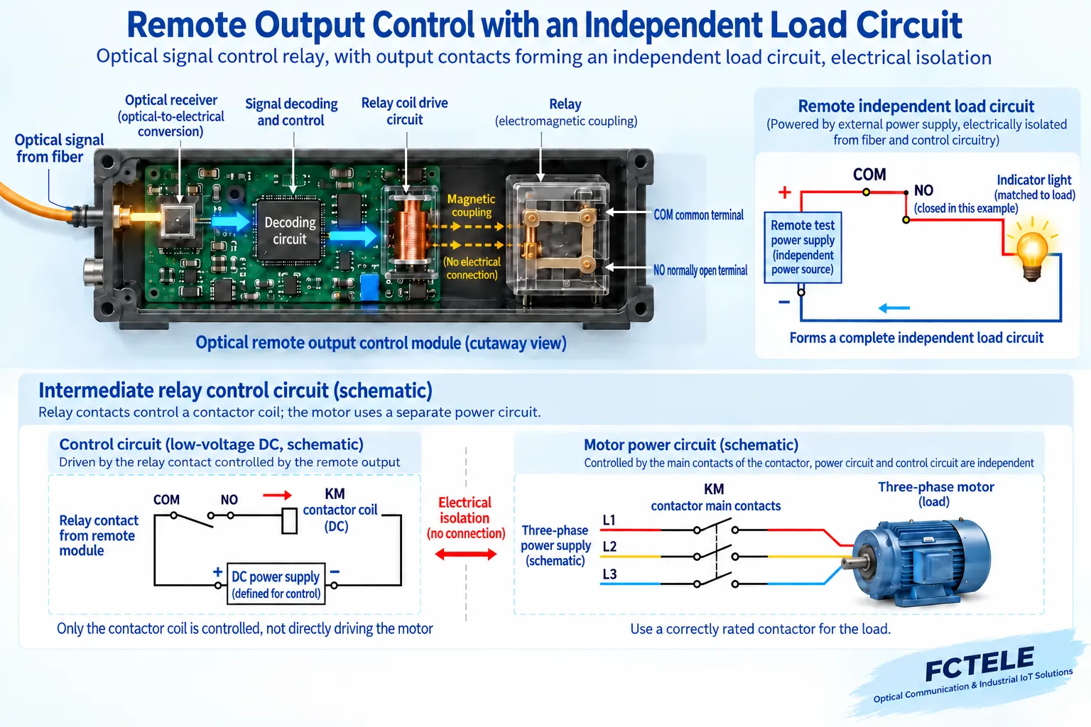
Relay contacts are controlled switches, and the external loop still needs power. Verify whether the common terminal and output terminal are connected correctly, whether the output is a dry contact or electronic interface, and whether the input conditions of the receiving device match. Using an appropriate independent test loop to verify contact opening and closing helps distinguish between output device and downstream wiring problems.
Check load starting current, inductive surge and output capability. Do not assume that a relay can directly switch all loads just because the static current is small. If intermediate drive and protection are needed, design according to the load nature; leakage from electronic output may also put a small load in an unexpected state, and should be verified according to actual interface conditions.
If both the output and controller input change but the software does not respond, continue checking acquisition mapping, program conditions, alarm confirmation and display refresh. Communication only sends the status to the boundary, and service processing is still completed by the receiving system. Do not bypass necessary interlocks in the control program just to see an action.
6. How to leave evidence for intermittent faults
Record the abnormal time, and correlate power supply, equipment action, optical path switching and environmental changes. Compare input waveform and output waveform to determine whether the input was not recognized, transmission was abnormal, or downstream did not acquire it. Replace only one known condition at a time, and save the results before and after replacement, to avoid replacing power supply, fiber and equipment at the same time and losing the basis for localization.
If the phenomenon only appears after connecting the site load, first compare the load with output capability, power supply and protection conditions, then compare using a matching test load. Normal contact opening and closing under no load only means this no-load check passed, and cannot be used to rule out contact problems under actual switching current. Inspection records should retain the site load model and operating conditions.
After recovery, retest each channel’s opening and closing, loss of communication and power-on again, and confirm that the test configuration has been removed. Deliver a table of phenomena, inspection methods, actual results and items to be verified. Do not declare repair just because all lights are finally on, and do not continue to write the fault phenomena of old video optical transceivers as the diagnostic basis for contact-only products.
Sources:Feichang FCP-K16G product documentation;Feichang FCP-K1/2 product documentation;Feichang FCP-K4 product documentation;TI digital input module design documentation;OMRON relay usage precautions;IEC 61000-4-5 surge immunity test description. The illustrations explain general mechanisms; they are not actual product photos, measured waveforms or certification documents.
Translated from the Chinese technical article. Source first published: 2019-12-27. Source last revised: 2026-10-13T13:13:08+08:00. Read the Chinese source
