


An RS485 bus connects multiple devices to one differential line pair so they take turns exchanging serial data according to an agreed convention. The core of a typical circuit is not a special plug, but the controller’s serial port, the transceiver and the actual cable working together. Understanding how each stage changes the signal lets you tell apart software bytes, chip logic levels and line voltages, and also helps you avoid treating RS485 as if it were one particular instrument protocol. This article explains the mechanism using a common two-wire half-duplex system; four-wire schemes and special interfaces need to be checked separately.
1. Looking at the bus starting from one byte
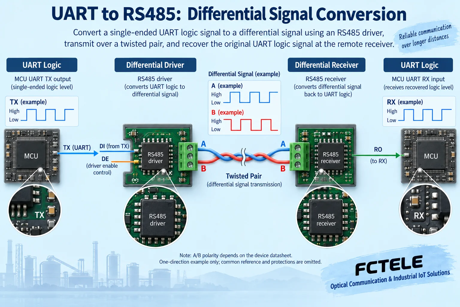
Suppose a controller reads an electricity meter; the software first forms a query message. The UART is the serial transmit/receive unit inside the controller. It arranges bytes into a string of bits according to baud rate, data bits, parity and stop bits, and then outputs logic levels from the transmit pin. This pin usually belongs to an on-board logic interface and cannot be connected directly to a long-distance RS485 cable. The UART decides how characters are arranged, while the RS485 transceiver is responsible for how those bits are expressed on the wires.
The receive direction is exactly the opposite: the transceiver first judges the line voltage difference and outputs a logic state, and then the UART recognizes the start bit and data according to the agreed timing. Even if the electrical waveform can be judged, inconsistent parameters can still cause garbled characters or frame errors. The application must also check the message address, checksum and the meaning of the data; the RS485 standard does not tell the meter which register stores temperature, nor does it automatically recognize the master’s command.
2. How the transceiver forms a differential signal
The transmitter drives the two lines according to its internal logic state, so that a distinguishable voltage difference appears between them. The receiver mainly compares the difference between these two lines, rather than looking only at the voltage of one line to ground. A twisted pair keeps the two conductors in a relatively similar environment along the route, so a portion of interference that is superimposed in common is easier for the receiver to suppress. Here, differential is an electrical observation method; it is not immunity to all interference, and it is not the ability to withstand any arbitrary potential difference.
Different manufacturers may name A, B, positive/negative and inverting terminals differently, so actual wiring must follow both sides’ terminal tables. Old articles that use one fixed voltage symbol to deduce the logic state of all devices easily lead readers to miswire. You should check the datasheet of the selected transceiver, the device wiring instructions and the receiving threshold conditions. The output during idle, short circuit and disconnection also differs because of fail-safe design, so one old chip’s threshold cannot be treated as a uniform rule for all products.
3. Why two-wire half-duplex needs enable control
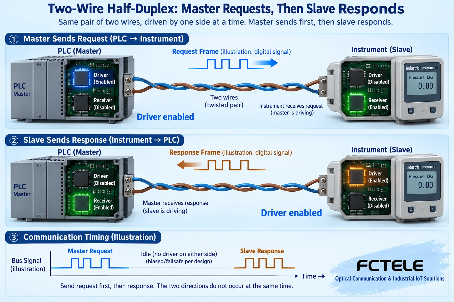
A common transceiver includes control pins such as transmit input, receive output and driver enable. The driver enable decides when the chip actively drives the bus; the receive control decides whether the internal receive path works. When the master sends a query, other nodes should not seize the line at the same time. After the master finishes sending and releases the driver, the designated slave returns a response. This is called half-duplex: the two directions share the line pair and usually need to be used in time slices; it is not one line for transmitting and another line for receiving.
Turning the enable off too early will cut off the end of the request, and turning it off too late may block the slave’s response. The software buffer being empty does not necessarily mean that the UART’s last stop bit has already left the pin. Hardware or software should control the direction according to the actual transmit-complete condition; automatic direction switching must also be verified against byte intervals, baud rate and device response time. The time blocks in the figure only show sequence, and no fixed waiting time for any model can be measured from the figure.
4. The cable gives the circuit propagation and reflection
A short stub and a long cable behave differently. An edge travels along the cable, and when it reaches a place where impedance does not match, reflection occurs, so the receiving end may see multiple changes. Termination is used to reduce this kind of phenomenon, usually considered around the two ends of the actual segment, and the resistance value must match the cable and device design. You cannot unconditionally add termination to every node; multiple resistors in parallel increase the driving load and may also make originally normal communication worse.
A trunk with short branches is a common wiring approach; overly long branches or passive star forks need special evaluation. Node count, distance, rate and edge speed constrain one another, so a certain maximum node count, longest distance and highest rate cannot be combined into a promise at the same time. When a branch or isolation is needed across areas, suitable active hubs, repeaters or fiber-optic schemes can be used, but these devices do not automatically add parallel-master capability to the application protocol.
5. What biasing, protection and reference conditions each handle
When no one is transmitting, the line may lack a sufficiently clear differential state. External biasing uses a resistor network to help establish an idle voltage, while a fail-safe receiver gives a definite output under specified abnormal states. Whether external biasing is needed should be calculated according to the whole bus, the built-in circuit and the load; fixed resistor values from old articles cannot be copied. Biasing solves idle determination, and termination solves reflection; the two are related but have different jobs.
Reference lines, shielding and protective grounding also cannot be mixed up at will. The transceiver still has an allowed common-mode range, and power and enclosure connections may change the potential relationship between the two ends. Isolation is used to cut the corresponding DC conduction path, and surge protection is used to limit transient stress; each needs to be designed together with the rest. A common Zener diode or resistor cannot simply replace a protection network that has been selected for the purpose, and the fact that data can be read once does not prove that the whole interface is already safe and reliable.
6. Understanding actual products with a minimal system
First use one master, one instrument and a short cable to verify a read-only query, record the transmitted bytes, received bytes and transmit/receive timing, and then add the field cable and nodes. Confirm the address, character format and termination status one by one. Do not apply power to unknown terminals when you do not understand the device, and do not casually connect lines at different potentials with an ordinary oscilloscope ground clip. When waveform measurement is needed, personnel with the proper conditions should choose a suitable differential measurement method.
The official Feichang Technology FCC-RD specification describes RS232 to RS485/422 conversion, active isolation and automatic direction control. It can serve as a concrete example for understanding that an external converter also contains a transceiver and control circuit, but it does not mean that every MCU board uses the same kind of chip. If extending to fiber optics, the format and mode of the serial-to-fiber modem should be checked separately; an RS485 copper bus, an optical port and an Ethernet port cannot be interconnected just by their appearance. At delivery, keep the terminal table, address table, configuration and continuous polling results, so that later people can troubleshoot along the same signal path.
Source verification:TI RS485 Design Guide;TI idle fail-safe note;TI isolated transceiver material (general principle);Feichang Technology FCC-RD specification;Feichang Technology FC2P-D/Q/R ring network product material. The illustrations explain general mechanisms and and are not actual photos, actual PCBs or measured waveforms of the corresponding products. Specific parameters and capabilities are subject to the corresponding model, version and delivery materials.
Translated from the Chinese technical article. Source first published: 2021-12-02. Source last revised: 2026-10-13T12:33:29+08:00. Read the Chinese source
