


A telephone optical transceiver does not simply replace a telephone line with fiber. It sends voice and states such as on-hook/off-hook and ringing to the other end, then restores them into electrical signals that a telephone or switch can use. When troubleshooting, first distinguish the roles of the telephone interfaces, then check the bidirectional optical path, and finally verify the entire call process; an optical port light being on does not mean the telephone service is working normally.
1. First understand how it transmits telephone calls
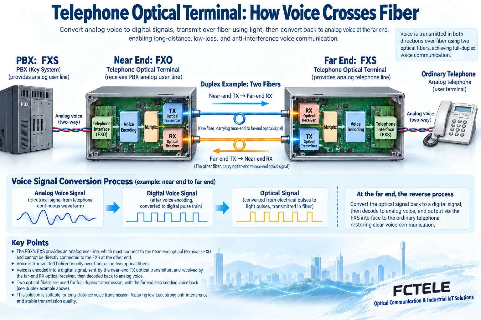
When an analog extension needs to be extended between two buildings on a campus, a pair of telephone optical transceivers can be placed between the PBX and the remote telephone. The near end receives the voice electrical signal, and after encoding/decoding and multiplexing, modulates it into an optical signal; the far end performs optical-to-electrical conversion and voice recovery. The reverse direction also has the same path, so usually both devices need to transmit and receive; it should not be simply understood as “one only transmits, one only receives.”
A call includes not only sound but also call control: whether the phone is off-hook, whether ringing is needed, whether the other party has hung up, etc. The equipment must also detect, transmit, and reproduce these states at the other end. If you can hear sound but there is no ringing, or if the line stays busy after hanging up, the problem is often in the signaling link, not necessarily a broken fiber.
This article focuses on point-to-point extension of ordinary analog telephones. Digital proprietary phones, IP phones, magneto telephones, E&M audio, and video optical transceivers have different interfaces and working methods, and cannot be directly applied just because they look similar. The figure is a general functional illustration and does not represent the internal circuit or measured results of any specific model.
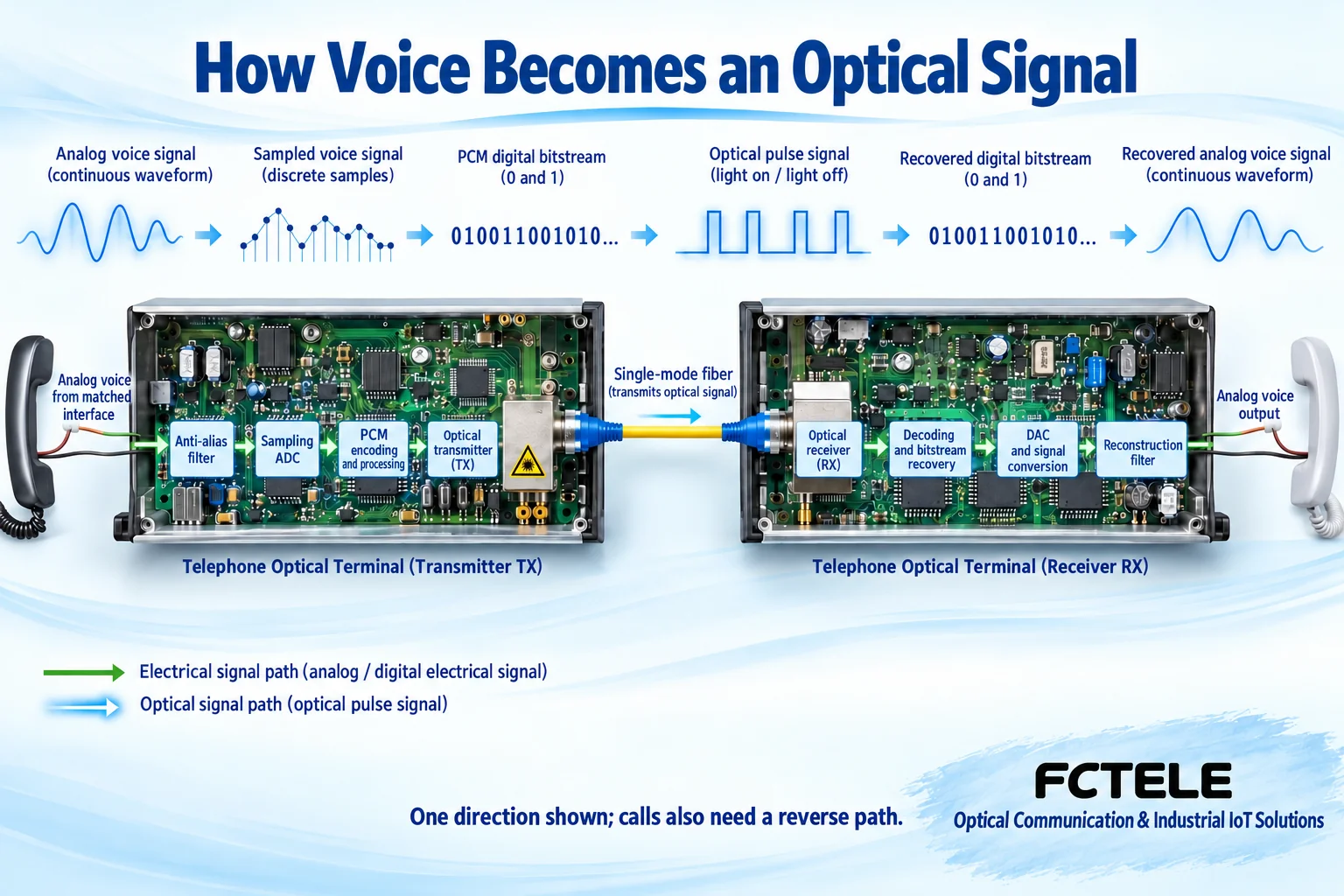
From continuous sound to bits, then from optical signal back to sound
Analog voice is an electrical signal that changes continuously over time. Taking a digital telephone transmission scheme using PCM (Pulse Code Modulation) as an example, the input first limits the signal frequency range, then samples over time, quantizes the amplitude, and encodes. Sampling is like recording the height of the waveform at fixed intervals, but it does not copy all sound details: filtering, sampling rate, and quantization rules together limit the information that can be recovered. G.711 is a telephone voice coding standard; the common 8000 times per second and 8 bits per sample correspond to 64 kbit/s per channel, which is not equal to the optical line rate of the entire device.
Multiple voice channels are organized into transmission data according to their respective channels, and states such as on-hook/off-hook and ringing also need corresponding transmission mechanisms. Multiplexing allows multiple services to share a bearer; it does not merge independent extensions into the same number. The receiving end must find the corresponding channel and recover it according to matching rules; if the channel or signaling does not match, sound may be heard but the call cannot be completed. The specific line format, clock, and whether E1 is used depend on the model and cannot be inferred from the name “telephone optical transceiver.”
The optical transmitter uses electrical data to control changes in light; the figure uses intensity changes to represent bits, explaining only one common digital optical transmission method. The photodetector at the receiving end first converts incident light into current, and the receiving circuit then amplifies, recovers timing, and makes decisions to obtain processable bits. The detector does not directly understand sound, nor can it fix all errors by increasing sensitivity. After demultiplexing extracts the corresponding voice channel, digital-to-analog conversion and recovery filtering form analog voice, which is then sent to the terminal by the telephone interface. Error correction, echo cancellation, and network management functions must be checked against the model; they are not capabilities that this basic process necessarily has.
The value of fiber is to extend services with lower line loss and less electromagnetic coupling. It does not mean the telephone will automatically upgrade to high-definition voice, nor does it mean propagation in light is necessarily faster than copper. Actual delay is also affected by encoding, buffering, and line length. Campuses, schools, and hospitals can extend compatible analog extensions, but video conferencing, telemedicine images, and home internet require their own corresponding service equipment. Call forwarding and voicemail are usually provided by the telephone service system and cannot be regarded as default functions of an ordinary telephone optical transceiver.
2. How FXS and FXO pair
FXS can be understood as “the side that provides the telephone line,” and FXO as “the side that uses the telephone line.” The FXS side provides line feed and ringing conditions; the FXO side connects to this line and presents states such as on-hook/off-hook. An ordinary analog telephone uses the FXO role, and the analog extension port of a PBX is usually the FXS role.
A typical connection is: the PBX analog extension port (FXS) connects to the near-end optical transceiver FXO port; the far-end optical transceiver FXS port connects to an ordinary analog telephone. First verify the port roles, then verify the channel number, wiring terminals, and wire sequence. The fact that an RJ11 can be plugged in only means the mechanical shape fits; it does not guarantee the signal type is correct. Do not directly connect two feeding ports, and do not treat a digital proprietary extension port as an analog extension port.
When the remote telephone goes off-hook, the remote FXS detects the loop change and transmits the state to the near end; the near-end FXO lets the switch see the corresponding off-hook state. For an incoming call, the opposite happens: the near end detects ringing, and the far end generates local ringing based on the received control state. Fiber transmits data and states; it does not directly “carry over” the high ringing voltage from the switch side. Dial tone still depends on the upstream switch or service system, and you cannot assume that all FXS optical transceivers independently provide dial service.
3. When selecting a model, do not only ask how many kilometers it can transmit
First write down the number of telephone channels, interface roles at both ends, existing switch type, caller ID and fax requirements, then determine fiber type, core count, interfaces, and power supply. Single-fiber devices require verifying the pairing relationship and bidirectional wavelengths; dual-fiber usually requires the TX at both ends to be correctly connected to the RX at the opposite end. Both sides must also belong to an interoperable transmission system; they cannot be considered compatible just because the wavelength or connector is the same.
Transmission distance is a specification under specific conditions; the actual link also includes connectors, splice points, bends, and aging loss. The received optical power should be within the allowed range of the device: too weak may lose the link, and too strong may overload the receiver. When long-distance equipment is used on a short link, the overload upper limit especially needs to be checked. You cannot promise that “for over-distance, just replace the optical module,” and you must also verify the module, electrical interface, transmission rate, and device support range.
SC, ST, FC, and LC mainly describe connector forms and cannot be used to determine the number of telephone channels or service bandwidth. The Ethernet port rate on a multi-service device is also not equal to the net bandwidth of the entire transmission channel. The E1 line rate is 2.048 Mbit/s, and “having one E1” cannot be interpreted as directly providing 10 Mbit/s of effective transmission. Network management, backup, and ring network functions must be confirmed model by model; having two optical ports does not mean ring protection is automatically available.
4. How to troubleshoot common symptoms step by step
1. All telephones are down at the same time.First check the power supply at both ends and common alarms, and record the optical port, device operation, and service indicator lights. Confirm the fiber connection, TX/RX relationship, and paired devices. For a common outage, check the common part first; do not start by replacing telephones one by one. The meaning of alarm names and light colors is subject to the manual for that model.
2. Only one telephone channel is down.Replace that channel with a known-good telephone and short telephone cable, and verify the channel correspondence at both ends. If the fault moves with the telephone or cable, handle the external components first; if it always stays on the same port, then check the channel configuration, port circuit, and switch extension port. Change only one condition at a time and keep records before and after.
3. There is no dial tone when off-hook.First connect a normal analog telephone directly to the corresponding PBX extension port to confirm the upstream can provide service, then restore the optical transceiver link. Check the FXO/FXS pairing, remote line, and whether the off-hook state is transmitted back. If direct upstream connection is also abnormal, handle the switch or service permissions first instead of continuing to adjust the optical path.
4. Calls can be made but incoming calls do not ring.Distinguish between “the switch did not send ringing” and “the far end did not restore ringing.” Test with a normal extension port, short cable, and a single telephone, and check whether ringing detection, output capability, and telephone load match. Connecting multiple telephones in parallel changes the load; a successful test with one telephone cannot be used to assume that multiple telephones can also ring stably.
5. Both sides are connected, but only one side can hear.Check the two voice directions, channel mapping, and interface configuration. If other channels on the same common optical path are normal, it should not be directly attributed to a broken entire fiber; judgment must be based on the specific device’s multiplexing and alarm mechanisms. Record whether it is an incoming or outgoing call, which side cannot hear, and whether the fault moves when ports are swapped.
6. Noise, low volume, or obvious echo.Compare a direct call with a call through the optical transceiver, shorten the local telephone cable, and check connectors, grounding, external interference, and interface matching. Gain should not be increased arbitrarily; excessive amplification may introduce distortion. Whether echo processing is configurable and how to set it must be based on the model’s supported capabilities.
7. Abnormal caller ID, fax, or hang-up release.Voice working does not mean all additional functions are compatible. Verify the caller ID format, fax support conditions, reverse polarity or other release signaling requirements, and separately test incoming calls, fax, and hang-up from both sides. Even if a device claims to support a function, it should be verified on the actual combination of PBX and terminal.
8. Occasional interruptions that recover after restart.Record time, temperature, power fluctuations, optical power, and alarms; do not keep only the conclusion “it recovered after restart.” If all channels are abnormal at the same time, check the common power supply and optical path; if it occurs only on a specific channel or service operation, check the port and signaling. Save the configuration before replacing equipment to avoid restarting masking the root cause.
5. Complete acceptance with a set of repeatable tests
First, on a short link that meets the optical power conditions, complete a minimal test with a pair of matching devices, one telephone channel, a known-good PBX extension port, and a known-good telephone. Verify off-hook, dialing, incoming ringing, answering, two-way voice, and hang-up release from both sides, then connect the on-site fiber and all channels. This separates device pairing problems from on-site link problems.
For each channel, record a correspondence table of “port number—extension number—opposite port”; initiate calls from both sides separately and check for crossed lines, false ringing, or busy conditions. Perform simultaneous multi-channel calls, caller ID, and fax tests as required by the project. Finally, verify fiber break or power failure alarms and recovery; if protection functions are available, test switching as agreed, and do not use another model’s recovery time as this device’s specification.
When measuring telephone lines, pay attention to ringing voltage and avoid touching exposed conductors; use suitable instruments and have personnel with the appropriate capabilities perform the work. Do not look directly into optical ports; perform optical power measurement, cleaning, and insertion/removal according to the manual. Save the topology, configuration, alarms, received optical power at both ends, and test results so faults can be quickly located after delivery.
6. How Feichang Technology products correspond to these requirements
You can start from pure telephone optical transceiver series by number of channels and installation form. The official website FCP-O16/FCP-S16 desktop 1–16 channel telephone optical transceiver explains the interface relationship of FXO connecting to the PBX and FXS connecting to the telephone, and lists caller ID, fax, and network management capabilities. When purchasing, you should still confirm the compatibility of the actual ordered configuration with the PBX and telephone; the principle diagrams in this article are not internal structure diagrams of that product and do not replace formal specifications or project acceptance.
In summary: first distinguish which interface supplies the line and which uses the line, then confirm that both voice and signaling can be transmitted in both directions, and finally finish with per-channel call and fault recovery tests. Do not judge system reliability only by distance, a lit light, or one successful call.
Coding reference:ITU-T G.711. This update completes the voice digitization, transmission and reception, applications, and capability boundaries of the old basic principle article; the illustrations are general illustrations, not internal structures or test records of Feichang Technology models.
Translated from the Chinese technical article. Source first published: 2020-04-10. Source last revised: 2026-10-13T13:55:23+08:00. Read the Chinese source
