


There is more than one way to build a 30-channel telephone solution: you can use a paired telephone optical multiplexer to directly extend 30 analog extensions, or you can use a telephone PCM access device to concentrate the voice channels onto an E1 digital interface, which is then carried by the existing transmission network. The first approach requires checking the telephone ports and optical line at both ends; the second also requires checking the E1 frame, clock, and signaling. When you see the words “30 channels,” you cannot treat these two connection methods as the same product.
What exactly is being counted in 30 channels
One telephone line is not a single one-way sound wire; it is a complete channel that can set up, carry on, and end a call. A 30-channel solution should clearly state how many actual interfaces exist at both ends, which ones are already configured, and whether all of them are allowed to work at the same time. The panel capacity, the service cards installed, and the usable channels may not be the same number, so the actual requirement should be written clearly when requesting a quote.
Digital voice solutions usually sample and encode each channel separately, then organize them for transmission according to channel position. The receiving side must know which channel the data belongs to in order to restore it to the correct telephone port. A shared optical path is not mixing 30 sounds into one combined audio stream; if the channel mapping is wrong, calls will cross over, and if the signaling is wrong, there may be sound but calls cannot be made or released properly.
How a paired telephone optical line is connected
A common way to extend ordinary analog extensions is to connect the FXS port of the PBX in the equipment room to the near-end FXO, and connect the far-end FXS to an ordinary telephone. The near end detects voice and status and sends them over the matched optical line to the far end; the far-end local interface provides power feeding and ringing. The other direction also carries voice and on-hook/off-hook information back, and both ends need optical transceivers and local power.
The FCP-O30/FCP-S30 details in the Feichang pure telephone category give the connection relationship between the 30-channel FXO and FXS ends. It can serve as a configuration entry point for extending analog extensions over fiber, but you cannot automatically infer from “30 channels” that an external E1 port exists. Optical protection, management, power, and installation form should be implemented according to the ordered version, and optional capabilities of the series cannot be treated as standard configuration.
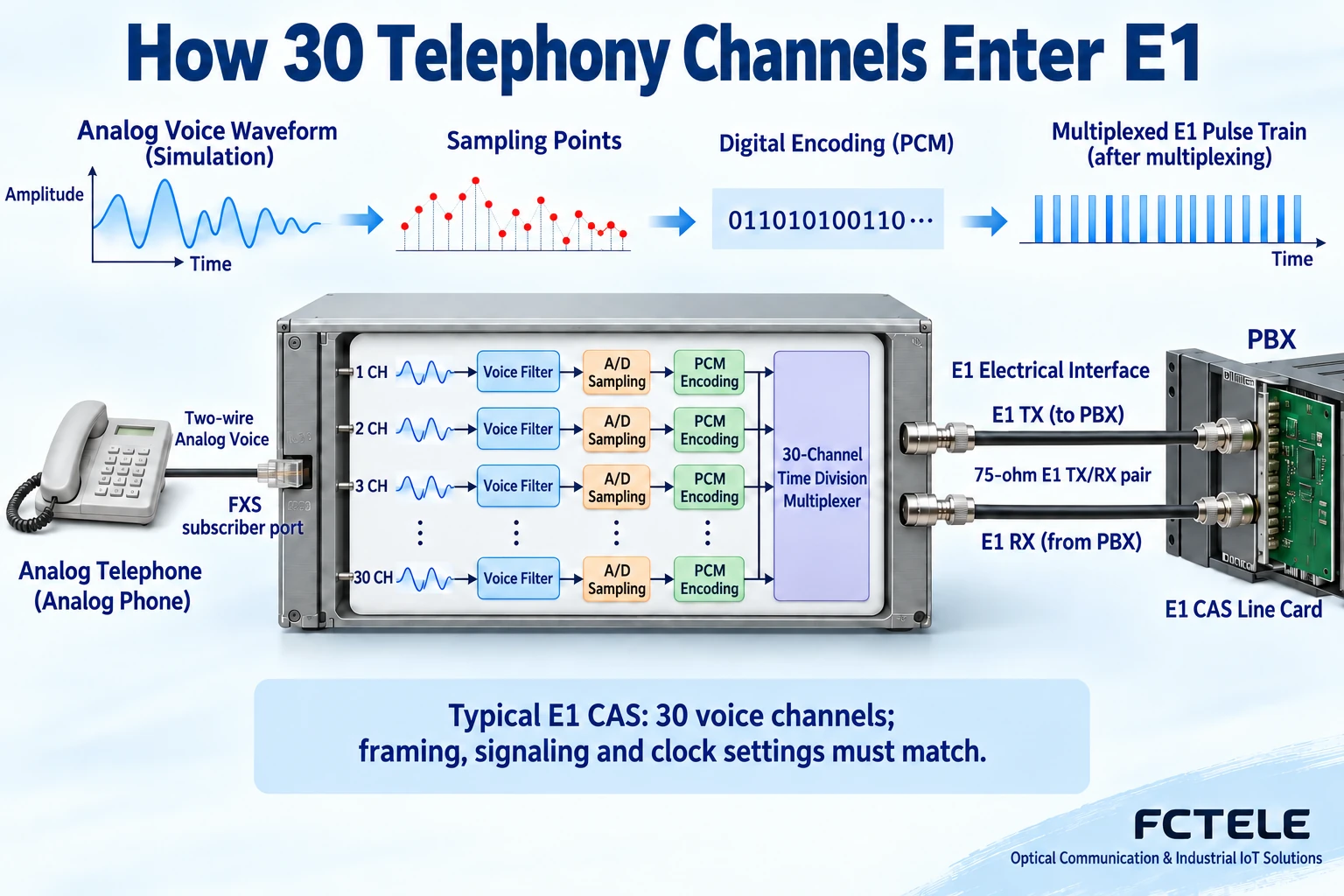
E1 PCM access is another path
When digital trunk or E1 transmission resources already exist, a telephone access device can concentrate voice onto E1. Ordinary telephones first connect to the corresponding subscriber line interfaces and do not plug directly into the E1 port. The far end can be a matching PCM access device or a confirmed digital trunk system; the connection method depends on the actual service and signaling, not just on finding a cable with a suitable connector.
The E1 physical electrical interface, encoding, frame structure, and clock all need to be checked. 75-ohm unbalanced and 120-ohm balanced are different interface conditions; coaxial cable and twisted pair cannot be mixed just by color. HDB3 is a line code type, not a telephone dialing protocol. A correctly configured physical interface still cannot replace matching time slots and call signaling.
Why traditional E1 is often said to have 30 channels, not 32
A common E1 framing structure has one frame every 125 microseconds, with 32 time slots of 8 bits each, and a line rate of 2.048 Mbit/s. In traditional channel-associated signaling telephone configurations, TS0 is used for frame synchronization and other information, TS16 is used for related signaling, and the remaining 30 time slots carry voice. Each voice time slot is 64 kbit/s, which is the source of the common statement that a single E1 has 30 voice channels.
CAS, or channel-associated signaling, organizes the corresponding call control states according to the rules and associates them with the voice channels. TS16 does not represent just one telephone voice channel, nor is it a time slot specifically for transmitting power. Different framing or signaling schemes may have other allocations, and this configuration cannot be treated as the only limit for all PCM devices. A 32-channel telephone device also cannot be directly equated with 32 E1 time slots.
How model information maps to configuration
The FCC-CS30 details in the Feichang E1 PCM channel-associated signaling category explain that it is oriented toward 1 to 30 voice channel access and E1-related signaling configuration, suitable for confirming item by item when E1 conditions already exist. It is different from the paired optical extension issue of FCP-O30/FCP-S30; you should first determine whether the site delivers telephone ports, E1 ports, or fiber, and then choose the corresponding route.
When using E1, clarify which end or which network provides the clock and how the device obtains the clock; if both ends run freely on their own, problems such as slips may occur. The framing, signaling status codes, channel order, and port types required by the far end should all be confirmed by both engineering parties. The fact that the official website has configurable signaling cannot be simplified into automatic compatibility with any PBX.
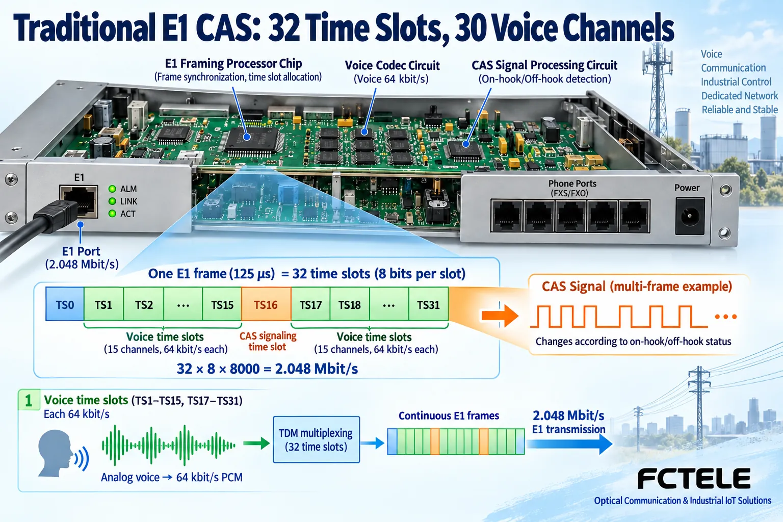
After commissioning, test each channel individually and also test concurrent calls
First verify one complete voice channel for incoming and outgoing calls in a controlled environment, then expand to all configured channels according to the channel table. Check ringing, two-way voice, dialing, on-hook release, caller ID if required, and fax; use different numbers to record the correspondence between the two ends. Then conduct simultaneous multi-channel calls according to project requirements, observing crosstalk, dropped audio, and resource usage, rather than only checking that one telephone call succeeds.
For the E1 solution, also check synchronization, line alarms, bit errors, and long-term clock stability; for the paired optical line, also test the received power in both directions and the allowed range. Schedule maintenance windows for fiber-disconnection, power-loss, and recovery tests for important telephone services, and leave alternative communication available. Deliver the model, version, configuration, port mapping, and test evidence to avoid confusing service channels and time slot numbers when cards are replaced in the future.
When 30 numbers already exist, first determine what is delivered in the middle
Suppose a project already has 30 PBX analog extension ports, the far end needs 30 ordinary telephones, and only dedicated fiber is available in the middle. You should first evaluate paired telephone optical extension, mapping each analog port one by one, rather than assuming by default that the existing extensions must also be put into an E1 trunk. If the carrier or existing system delivers an E1 digital line, then you enter the verification path of PCM access and digital trunk. Both solutions may have “30 channels” in their names, but their interface lists and responsibility boundaries are clearly different.
When the original materials mention both 8-channel modules and 30-channel complete units, ask what each slot can hold, how the total resources are arranged, and how many ports are actually delivered; you cannot simply add the two numbers together. When adding other data services, also confirm whether they use independent resources or share the bearer. Once the configuration is determined, the test record should state the channel, the corresponding extension, and the digital tributary conditions, so that installers do not treat the telephone number, chassis port number, and E1 time slot number as completely identical numbers.
Sources:Feichang product material 1;Feichang product material 2;Feichang product material 3;Feichang product material 4;Principles and standards material 5. The schematic diagrams are general principle illustrations, not actual products, customer cases, or measured tests. Interfaces and specifications are subject to the ordered configuration and on-site acceptance.
Translated from the Chinese technical article. Source first published: 2021-06-07. Source last revised: 2026-10-13T13:55:23+08:00. Read the Chinese source
