


Both use fiber, but the entry point handles different things
The duty room wants to reach a remote telephone, and the monitoring room wants to see a remote camera image. Both tasks may use optical transceivers. The similarity is that the applicable electrical interface service is organized onto an optical line and then restored at the other end; the difference is that telephone also involves feeding power, ringing, and on-hook/off-hook states, while video involves format, picture, and synchronization. Comparing only transmission kilometers cannot determine whether the equipment can connect to the original system.
A telephone optical transceiver is not a universal jack into which any sound, network, and camera can be plugged. A video optical transceiver is not compatible with any video interface just because an image appears. First write down the service source, terminal, and roles at both ends to separate shared fiber from service compatibility. This article mainly compares digital optical transmission of analog telephone interfaces and CVBS analog video. SDI, HDMI, and VoIP should be checked separately for their corresponding mechanisms.
Telephone interfaces not only transmit sound but also maintain call relationships
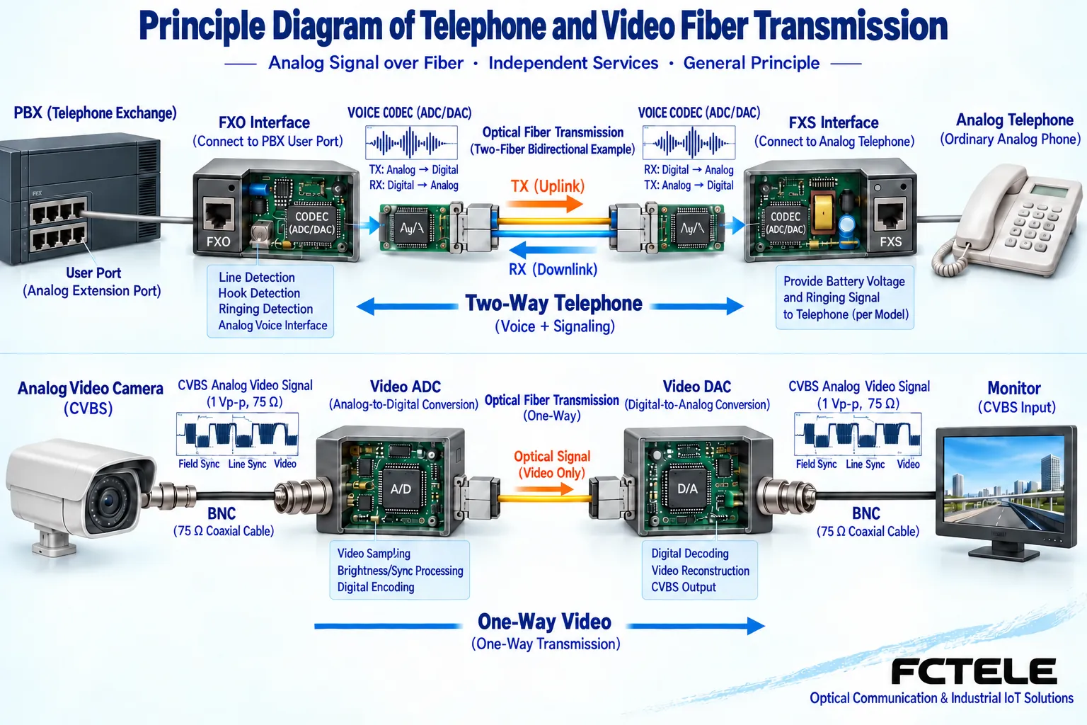
During an ordinary analog telephone call, speech forms a corresponding electrical signal, and the telephone system also needs to recognize states such as off-hook, on-hook, and ringing. Transmission equipment supporting this interface must receive speech and signaling according to its design and provide corresponding functions at the other end. If only sound passes but ringing cannot occur, or ringing can occur but a call cannot be established, then telephone extension is not complete.
FXS and FXO describe telephone interface roles. The FXS side usually provides corresponding line functions to the telephone terminal, and the FXO side connects to the subscriber line side of a switch that provides these functions. Wiring must be confirmed according to the equipment definition; do not assume arbitrary connection just because both ports use RJ11. Telephone ringing involves actual voltage. Do not let an ordinary video port withstand a telephone line, and do not randomly test connections on unknown powered ports.
Voice digitization and optical transmission are different stages
Digitally processed telephone transmission can first sample speech into a digital representation and then organize channels in a way supported by the equipment. Sampling describes when measurements are taken, and quantization describes how amplitude is expressed; line coding and optical modulation are responsible for sending data to the far end. The receiving end restores speech and necessary states, and then the telephone interface circuit maintains the line conditions required by the terminal.
Specific products may use different voice coding, multiplexing, and signaling processing, and a unified internal structure cannot be inferred from the name. Traditional PCM channels and VoIP services over IP networks are also different: the former is transmitted according to corresponding circuit organization, while the latter also involves network packets and a session system. A telephone optical transceiver having a network port does not prove that the telephone will automatically become a network extension that can register with any VoIP platform.
Video input focuses on continuous waveforms and image timing
CVBS composite video expresses information such as picture and synchronization in a voltage waveform. A digital video optical transceiver can first receive, filter, and sample, then organize the data onto an optical link; the receiving end extracts samples and reconstructs the corresponding analog output. It extends an existing video and is not responsible for capturing images, recognizing license plates, or saving recordings.
Using analog-to-digital conversion does not mean that telephone and video have the same input range, bandwidth, and sampling requirements. Telephone RJ11, video BNC, audio RCA, and serial port terminals are different objects. A video optical transceiver being digital internally does not automatically mean that the receiving end outputs SDI, HDMI, or Ethernet; external interfaces and internal transmission should be described separately, and adapter cables cannot replace necessary electronic conversion.
To compare direction, look at which service is bidirectional
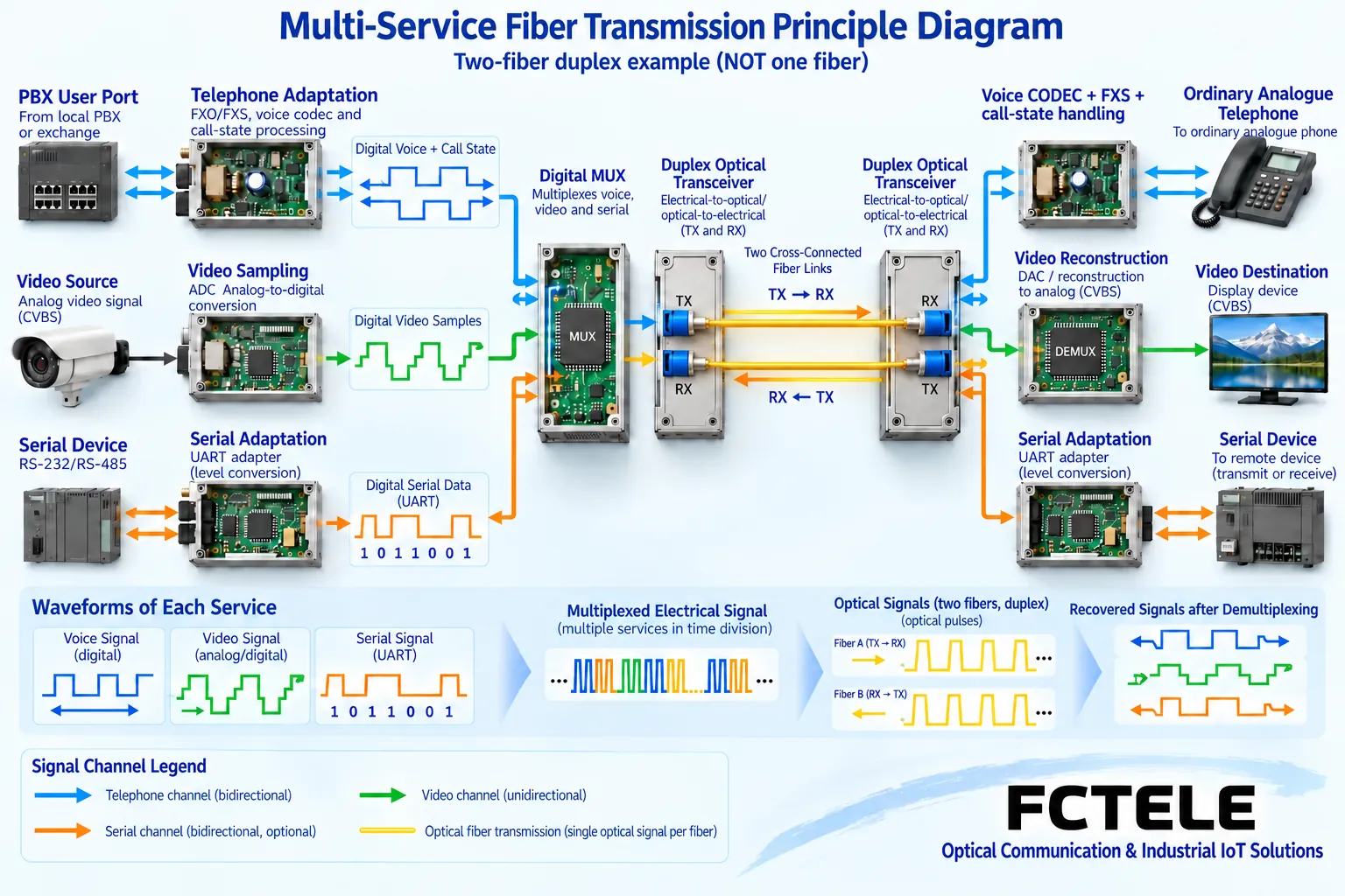
A telephone call usually requires both parties to transmit voice simultaneously, and call status also needs corresponding handling. Surveillance images are often sent from the camera to the center, while PTZ commands may return in the opposite direction to the site. When a product is marked bidirectional, ask clearly whether it is bidirectional voice, bidirectional serial, or video in two directions; the quantity and direction of different services cannot be borrowed from each other.
Assume a device has four video channels and one reverse control channel. This does not mean it has four telephone channels, nor does it mean the receiving end can capture four more video streams. Even if telephone channels are numbered the same as video channels, they each have independent interface meanings. When designing, drawing each service as a clear arrow and listing source, destination, and parameters is more helpful for procurement and troubleshooting than just writing one fiber for all.
Multi-service products combine interfaces rather than eliminating differences
Some optical transceivers simultaneously provide telephone, video, serial, Ethernet, or switch contacts. They are first adapted separately, then multiplexed according to design, and restored separately at the far end. A shared optical transmission section cannot prove that the interfaces are interchangeable, nor can it prove that any service can be expanded indefinitely. Capacity, options, and pairing conditions still need to be based on the actual ordered combination.
The Feichang FCV-V4T/R video product details list four forward video channels and multiple configurable additional services. The Feichang multi-service telephone category shows combinations such as telephone with Ethernet or serial. Their value lies in centralized transmission according to requirements, and the characteristics of one series cannot be transferred to another series. Checking with the manufacturer-confirmed port table is key to avoiding optional functions being mistaken for all standard features.
How Feichang telephone models fit into actual solutions
For example, the relevant details for the official website FCP-O4R4/FCP-S4R4 target one to four telephone channels and corresponding serial combinations. When the site needs telephone return and instrument control, this can be used to check telephone roles, channel counts, and serial configuration; optional structures or network management mentioned on the page should also correspond to the ordered version, and all terminal definitions should not be derived from the model letters alone.
If camera images are also needed, separately check the video input format and corresponding video products, or choose a comprehensive model that clearly includes both types of services. The optical port, power supply, and installation form provided by the manufacturer can only be used for that confirmed configuration. Do not randomly pair a telephone transmitter with another video receiver just because both are Feichang products; the protocols and service organization at both ends must be compatible.
During commissioning, use different evidence to prove the two types of services
For the telephone link, first establish a short link using matching telephone and switch-side conditions, and verify incoming calls, outgoing calls, ringing, on-hook/off-hook, and voice in both directions. If caller ID or other functions are needed, verify them separately as agreed; one successful dial-out does not prove all support. Measurement and wiring must comply with actual telephone interface requirements, and unknown ports should not be directly connected to an ordinary network card or video tester.
For the video link, check the real source format, each channel’s picture, synchronization, dynamic scenes, and recording end. If PTZ control is included, then verify the address, control protocol, and actions. Only after the two types of services are normal separately should the required concurrent combination be performed. If all channels are interrupted at the same time, check the common power supply and optical path; if only the telephone does not ring or one video channel has no image, investigate along the corresponding service section, and do not use the same indicator light to replace all diagnostics.
Optical paths and delivery records remain the common foundation
Both types of equipment require checking the fiber type, transmit/receive pairing, connectors, loss, and upper and lower limits of received power. Fiber does not provide arbitrary power to telephones or cameras; the actual power supply method and port feeding should be confirmed separately. Cabinet protection, grounding, and end-face cleaning should be performed according to the manual. Do not look directly into optical ports, and do not extend the non-conductive nature of a fiber section into absolute lightning protection for the entire equipment.
At delivery, leave the models at both ends, port roles, channel directions, cable numbers, and actual service test results. Maintenance personnel should be able to understand what each interface is transmitting and which condition is provided by which device. The common point of telephone and video is extending services through a matching link; the real difference that determines selection is the entry signal, processing mechanism, terminal roles, and the method of separately proving service success.
Data note: The principle diagrams have been checked against technical content and are used to explain general mechanisms. They are not physical product photos or measured records. Specific interfaces, modes, and capabilities are subject to the selected model, version, and on-site verification.
Verification materials:Feichang FCV-V4T/R four-channel video product information
Feichang FCP-O4R4/FCP-S4R4 telephone and data product information
Translated from the Chinese technical article. Source first published: 2022-07-14. Source last revised: 2026-10-13T13:25:53+08:00. Read the Chinese source
