


First, write down clearly which signals are to be accepted
The role of a video optical transceiver is to send the video signals supported by the device into a fiber link, and then restore the corresponding output at the other end. The technical specification must first answer what the input is and what the output is, rather than first comparing marketing terms such as high definition, digital, or industrial grade. CVBS is composite video that combines image and synchronization information in a continuous voltage. SDI is serial digital video transmitted in a specified format. HDMI also includes control processes such as display capability negotiation. They require different test methods.
An executable specification table should state the service interfaces, video system or format, number of channels, transmission direction, additional audio and control channels, optical port configuration, power supply, and installation conditions. For example, four channels of forward CVBS video plus one reverse RS485 control is a different requirement from extending one 3G-SDI video signal. Even if both use BNC connectors, compatibility cannot be inferred from that alone. The model, hardware version, and optional items should correspond to the delivered equipment.
Analog video bandwidth determines whether details can be preserved
The bandwidth of analog video can be understood as how fast voltage changes the device can preserve. Image details correspond to faster signal changes. When the transmission circuit attenuates high-frequency components more strongly, fine lines and edges may become softer. Frequency response describes how the amplitude of different frequencies changes after passing through the system, and it should be read together with the specified test conditions. A single bandwidth number alone cannot summarize all image quality performance.
During measurement, a test signal source suitable for the system and a video analyzer can be used to compare the input and output multiburst, amplitude, and related waveforms. Load impedance, cable length, and test termination will affect the results, and these must be noted in the record. If an oscilloscope is used for observation, first confirm that the instrument bandwidth, probe, or input termination method is suitable for the signal under test. Connecting two terminals casually to the same output may change the load and produce amplitude problems that are not caused by the optical transceiver itself.
Sampling and quantization explain the boundaries of digital transmission
A digital optical transceiver that transmits analog video usually first limits the input bandwidth, then uses an analog-to-digital converter, ADC, to sample at specified moments and convert voltage into digital values. An anti-aliasing filter limits excessively fast changes from entering the sampling system. At the receiving end, digital processing, a digital-to-analog converter, DAC, and reconstruction filtering restore the analog output. In this chain, the fiber carries digital data, while the camera and monitor ends can still use analog video.
For band-limited signals, the sampling frequency and the highest signal frequency need to meet the requirements of sampling theory and practical filter design. Real circuits also need transition bands and margin. The number of quantization bits determines how finely values are divided, but the effective resolution is also affected by noise, reference voltage, and circuit performance. Therefore, one cannot promise that the output is exactly the same as the input based only on the nominal bit count or the words digital transmission, and even less can an analog camera thereby become a network camera.
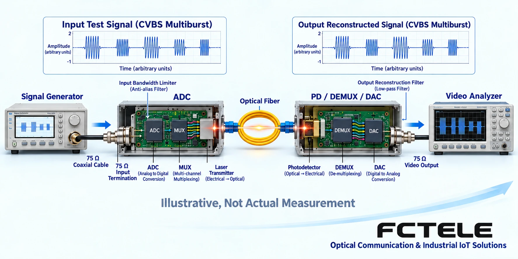
Brightness, color, and synchronization should be checked separately
In addition to image brightness, CVBS also contains synchronization information that lets the receiving device position the picture correctly. When the average picture level changes with large-area light and dark changes, whether DC restoration and synchronization processing are stable is an important factor in whether the picture jumps or shifts. Testing cannot be limited to playing one static color bar. Light and dark pictures should also be switched according to the agreement, and synchronization retention should be observed. The timing of different systems should be checked separately.
Differential gain and differential phase describe the changes in chrominance signal amplitude and phase under different brightness conditions, and they may affect color saturation and hue. They are not simply network packet loss rates, and they are not suitable to be directly applied to all SDI or HDMI devices. Which indicators and allowable ranges are used for acceptance should come from the model documentation and contract requirements. When the corresponding instruments and test conditions are not available, visual judgment that the color looks normal should not be written as these indicators having passed.
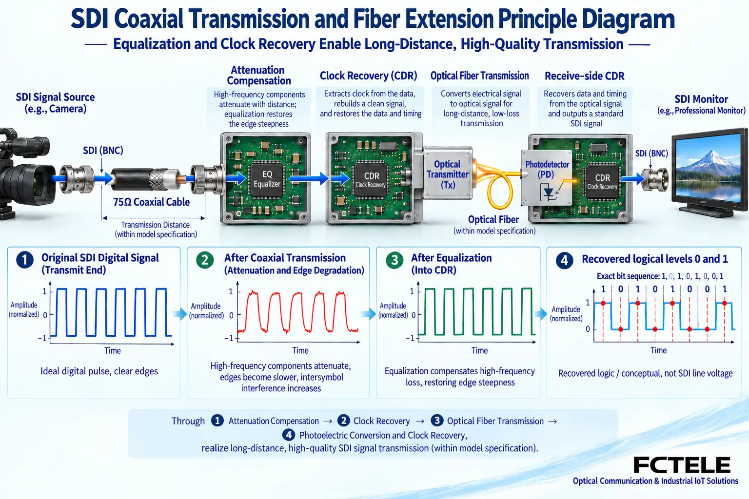
SDI checks format, line quality, and clock recovery
SDI specifications should state the corresponding standard, rate, and actual video format at the same time. Even if the resolution is the same, different frame rates or mapping methods may still be incompatible. SMPTE SDI standards roadmap materials can help explain the relationships among different standards, but they cannot replace the device support table. The Feichang Technology FCVH-V1b product documentation belongs to the 3G-SDI device range, and it cannot be concluded from that alone that it can transmit any higher-rate video.
A coaxial link may attenuate faster signal changes. An equalizer is used to compensate for loss within a certain range. A clock and data recovery circuit, CDR, recovers decision timing from the received data and then decides each bit. An eye diagram overlays waveforms on a repeated timing basis to observe characteristics such as sampling margin, and it requires suitable instruments and measurement conditions. On-site acceptance should record the actual format, coaxial segment length, lock status, and errors that the instrument can check, rather than replacing serial link testing with analog video bandwidth indicators.
HDMI also requires verifying the negotiation process, not just the picture
The capability of an HDMI link is limited jointly by the source, transmitter, receiver, cable, and display. EDID is information by which a display declares which modes it supports. HDCP is a protection and authentication mechanism used by certain content. A receiver indicator light only shows part of the link status and cannot prove that these processes succeeded. Resolution, frame rate, color format, and audio mode should be checked as a combination, not merely written as supports 4K.
Testing can start from a basic format that both sides are confirmed to support, then switch to the modes required by the project. Record normal display, hot plugging, power cycling, source switching, and authorized playback of protected content, without bypassing the protection mechanism. If the model has additional USB, serial port, or independent audio functions, their direction and support range must also be checked separately. A working mouse does not mean all USB cameras work, and normal video does not mean every control channel is normal.
Optical power and multi-channel concurrency determine engineering margin
For optical port specifications, at least check single-mode or multimode, interface type, operating wavelength, single-fiber or dual-fiber configuration, and the matching relationship between the two ends. The receiving end has both a minimum usable optical power and a possible overload upper limit. The measured received power should fall within the range specified by the device, and design margin should be reserved in light of the optical cable, connectors, splice points, and maintenance changes. A lit optical link indicator alone is not enough to conclude that a long-distance link is reliable under all operating conditions.
Multi-channel devices should be tested with all agreed channels working at the same time. The Feichang Technology FCV-V4T/R documentation describes four channels of video and auxiliary services expanded according to configuration, and it is suitable for establishing input-output mapping channel by channel on that basis. Its optional functions cannot automatically be extended to all models. In addition to per-channel testing, concurrent audio, control, and video should also be tested to observe whether services affect one another. The number of channels should be counted according to actual inputs and outputs, while the number of fiber cores should be counted according to the optical port configuration. These are not the same number.
Write acceptance results as a reproducible record
Before acceptance, save the model, version, configuration, wiring diagram, and instrument information. First establish a baseline with a short link, then connect the on-site fiber and terminal equipment. Each record includes the test signal, format, direction, load, duration, and judgment criteria. When a problem occurs, locate it section by section according to signal source, service wiring, optical link, and receiving output. After replacing equipment or changing parameters, note what was changed, to avoid changing multiple factors at once and making reproduction impossible.
Power supply, grounding, protection, environmental conditions, and electromagnetic compatibility requirements should also be checked according to the project and product documentation. When certification or test reports are required, the specific models, versions, and items covered should be checked. A web page saying industrial grade does not mean that all requirements have been met. Finally, record the visible picture, service interoperability, measurement indicators, and applicable conditions separately. A technical specification formed in this way is easier for procurement, construction, and maintenance personnel to use, and it can also show which conclusions have been verified and which still require additional testing.
Documentation note: The principle diagrams have been checked for technical content and are used to explain general mechanisms. They are not product photos or measured records. Specific interfaces, modes, and capabilities are subject to the selected model, version, and on-site verification.
Verification materials:Feichang Technology FCV-V4T/R four-channel video product documentation
Feichang Technology FCVH-V1b SDI product documentation
SMPTE SDI standards roadmap materials
Analog Devices visual effects of video parameters
Translated from the Chinese technical article. Source first published: 2024-05-28. Source last revised: 2026-10-13T13:25:53+08:00. Read the Chinese source
