


First, write down the service direction and device roles clearly
When an E1 converter cannot communicate, first write down the local service, the bearer channel and the remote service, then observe the alarms at both ends at the same moment. Ethernet passing through a dedicated E1 line, an E1 circuit passing through an IP network, and V.35 data entering E1 all handle different objects. Troubleshooting cannot force every device into one DIP switch table, and even less can an E1 port that looks similar be treated as an Ethernet port.
This article starts from the common part, the E1 interface. The E1 line rate is 2.048 Mbit/s. The receiver must not only read out the bits but also recover the timing; framed services also need to find the frame boundary and the correct timeslots. An optical port light being on, the network management being able to log in, or a switch being able to ping only means one layer meets its condition; it cannot prove that the circuit service has recovered.
Preserve the fault scene, then check power and physical interfaces
First record the model, firmware, configuration at both ends, fault time, current and cumulative alarms, and whether cables were changed, timeslots were adjusted or the bearer path was switched before the fault. A restart will clear some clues, and restoring factory settings may also lose the channel mapping; do not treat repeated restarts as the first step. Service tests, cable unplugging and loopbacks should be scheduled in a maintenance window, and a rollback configuration should be kept.
E1 commonly has 75-ohm unbalanced coaxial and 120-ohm balanced twisted-pair interfaces; the cable, port and impedance must match. The transmit side connects to the opposite end’s receive side, and the reverse direction is checked independently; an RJ45 shape does not mean the pins follow Ethernet. Check the product wiring table to confirm the correct wire pairs, connectors and any necessary impedance adaptation. Check the power supply voltage, polarity and grounding according to the selected version; do not wire according to another product’s documentation.
What LOS and AIS each tell you
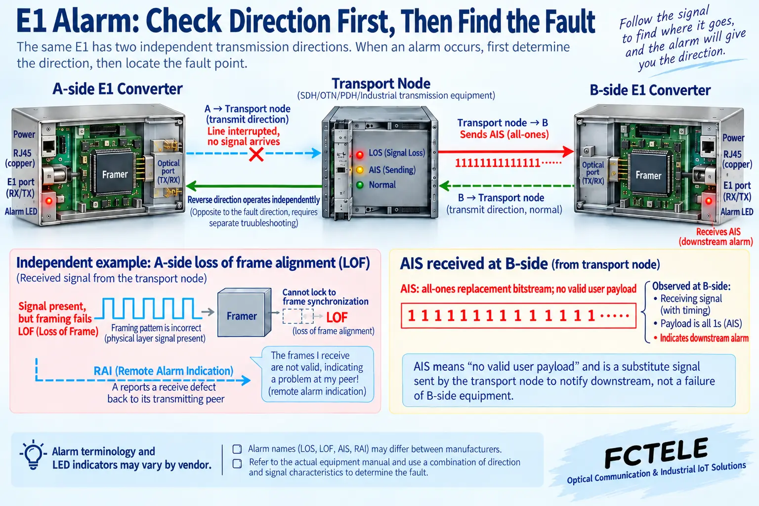
LOS is Loss of Signal, meaning the corresponding receive end has not detected a line signal that meets the criteria. A broken cable, reversed transmit and receive, no output from the upstream device, wrong wire pairs or receive conditions beyond the limit can all cause it. Start from the receive direction of the alarm end and check upstream, using a known-good short cable or test source to narrow the range; LOS does not directly mean this device’s hardware is damaged.
AIS is the Alarm Indication Signal. When some upstream transmission segment fails, the device may send an all-ones replacement signal downstream, indicating that the original service has been damaged. Seeing AIS at the receive end means that a corresponding alarm pattern has arrived; it cannot simply be concluded that “the fault must be at the farthest end.” Draw the signal propagation direction and check segment by segment who generates the AIS and what happened upstream of it, so the root cause can be found.
Different devices may use lamp names such as LFA and LOF, and the alarm criteria and display methods also differ. First distinguish current alarms from historical counts, and receive alarms from remote-reported alarms, then compare with the manual for this model. Third-party transceiver chip documentation can explain the principle, but it cannot prove that a particular Feichang Technology device has all the same indicator lights or thresholds.
Signal present but loss of frame alignment: check framing and timeslots
LOF or the corresponding loss of frame alignment alarm usually means the required frame alignment cannot be maintained. At this point pulses may already be received, and the problem may still come from a mismatch between framed and unframed modes, a mismatch in frame structure or CRC4 setting, or it may be caused by severe line errors. First improve the physical layer, then check the service mode; do not randomly change DIP switches just because there is loss of frame alignment.
A framed E1 has thirty-two eight-bit timeslots per frame. TS0 is used for frame alignment and other overhead, and whether TS16 is occupied by signaling depends on the service mode. The timeslots used at both ends, the starting position, the number of channels and the mapping must correspond. Some devices provide arbitrary timeslot selection, while some only provide fixed modes; “supports E1” does not mean it can be rearranged arbitrarily. When line alarms disappear but application data still does not pass, check whether the wrong service channel is being sent.
RAI is a type of remote alarm indication mechanism, which can help determine whether the other party’s receive side has a corresponding problem. It is a status reported by the other party, and does not mean that this end has already seen the specific bad point. Analyzing it together with both sides’ transmit and receive directions and alarm times is more useful than recording only one red light.
Intermittent errors and slips: check the timing relationship
The clock source should be clear and traceable along the entire circuit. The appropriate local, line-recovered or external clock mode needs to match the upstream network and the service-end role. In a point-to-point test, one end providing the reference and the other end following is a common arrangement, but “only one end may be local clock in all scenarios” cannot be written as a general DIP switch rule; in a live network, timing may be provided by the operator or a public reference.
If the read-in and read-out frequencies differ over the long term, the elastic buffer will gradually become full or empty, and slips may occur, meaning corresponding data is dropped or repeated to maintain the output. This is not the same phenomenon as random line errors. Record how the count changes over time, then check the reference source, the clock loop and the behavior after loss of reference. NTP making the management system show the correct date does not prove that the E1 line timing is qualified.
E1 over IP also needs checking for packet loss, out-of-order packets and changes in arrival interval. Deepening the jitter buffer may increase waiting, but it cannot recover service that has already been lost. If Ethernet goes through an E1 bridge, continuous overload and multi-channel delay differences need to be checked, and the configuration of a circuit emulation gateway should not be applied.
What a loopback test can prove, and what it cannot
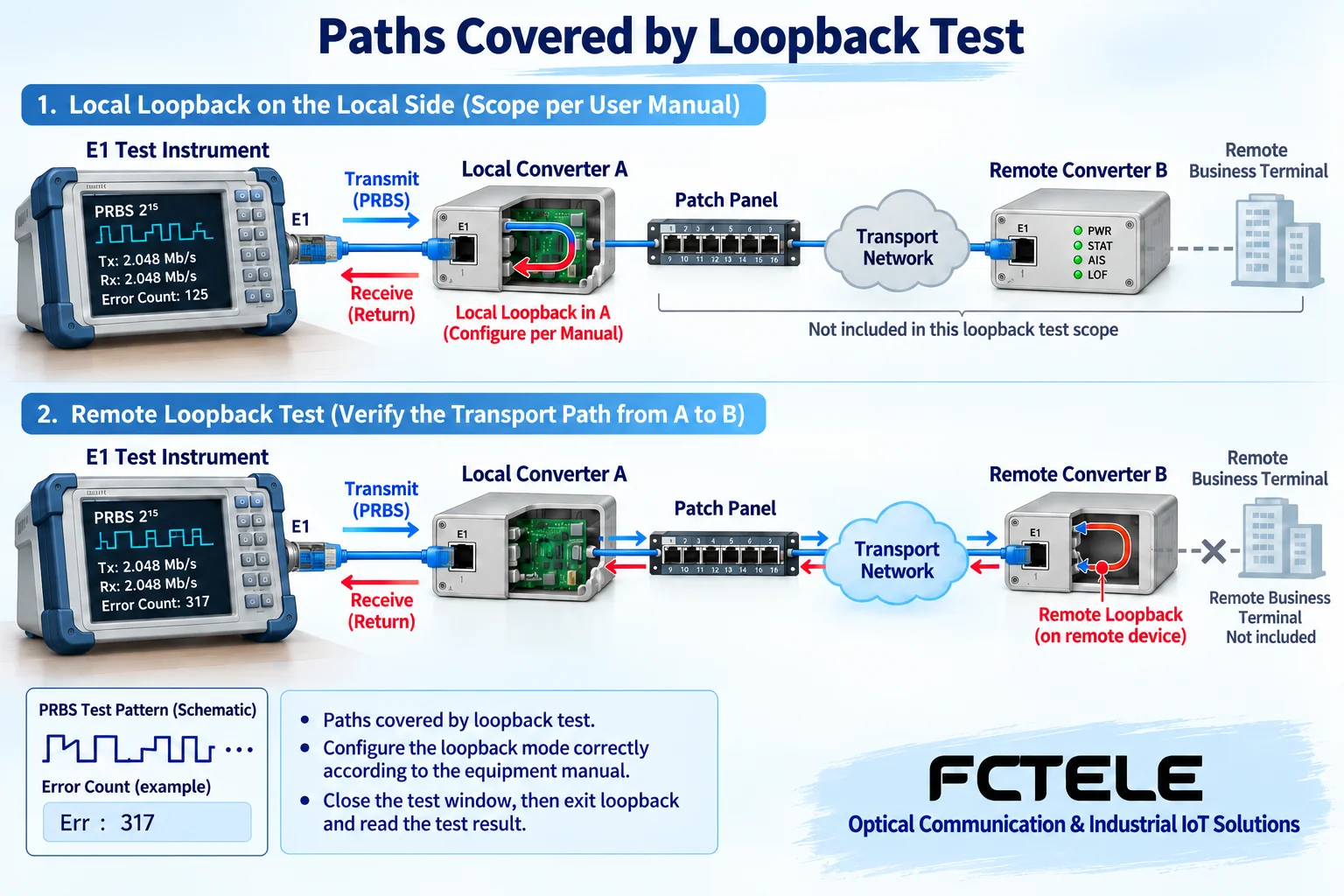
A loopback folds back the data path at some point, either transmit or receive, so the test end can check the returned result. A short port loopback, a line-side loopback and an internal device loopback have different coverage; what is also called a remote loopback may have different fold-back points. Before testing, draw the instrument, interface, cable, transmission network and fold-back point, and make clear which devices are still outside the test path.
First test on a short link according to the manual, then gradually include the patch panel, transmission path and remote device. The test pattern, framing and CRC conditions must match the test end. Seeing LOS disappear alone cannot prove that all circuit parameters are qualified, and passing a short loopback cannot prove that the remote terminal not included is normal. Do not directly inject a pseudorandom test pattern or perform a service-carrying loopback on a production circuit; cable continuity measurement should be done under the condition of safe power-off and disconnection.
For example, the Feichang Technology FCC-E16G3F2 documentation lists local and remote E1 line-side loopback, alarm display and timing selection, making it convenient to test the bridge and the external E1 bearer separately. These are listed functions of that model and cannot be transferred as the default capability of all converters. Confirm the specific ordered version and operating method before executing, to avoid service interruption caused by the test action.
Finally verify the service and leave a reproducible record
After exiting all loopback and test pattern modes, check whether alarms are cleared and whether counts continue to grow, then verify the actual two-way service. A bridge should record traffic, frame length, number of channels and dropped frames; a synchronous serial port should verify the data and clock directions; circuit emulation should verify continuous output and application quality under a real bearer load. Saving only one pass/fail result is not enough to judge long-term stability.
The acceptance record includes the test start and end time, covered path, parameters, observed errors and recovery process. First fix the physical conditions, then handle framing and timeslots, timing, bearer and application; this usually narrows the problem to an explainable segment. If it still cannot be located, submit both sides’ configurations and alarm trends, rather than only describing “the device does not communicate.”
Documentation note: The principle diagrams have been checked against the technical content and are used to explain general mechanisms; they are not product photos or measured records. The specific interfaces, modes and capabilities are subject to the selected model, version and on-site verification.
Reference materials: ITU-T G.703: Electrical characteristics of digital interfaces
ITU-T G.704: E1 and T1 frame structures
Analog Devices DS2155: Line receive, alarm and loopback mechanisms
Feichang Technology FCC-E16G3F2 bridge: alarms, timing and loopback
E1 converter classification and selection
E1 over IP encapsulation and clock recovery
Translated from the Chinese technical article. Source first published: 2019-10-08. Source last revised: 2026-10-13T13:25:53+08:00. Read the Chinese source
