


Four-port expansion serves one USB host
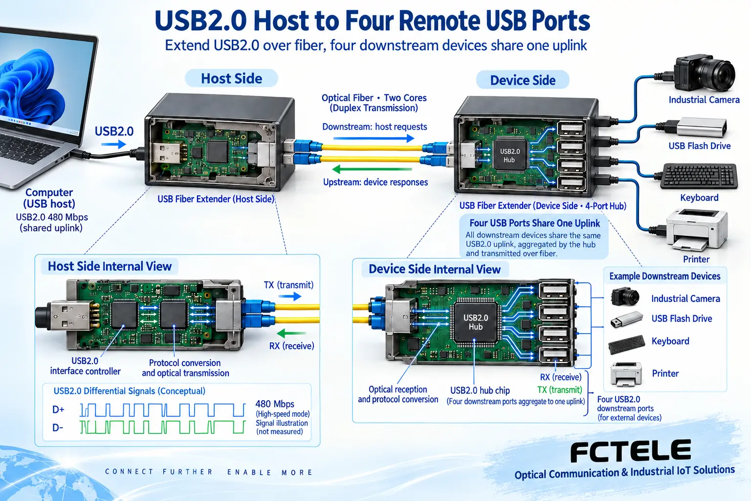
A USB 2.0 optical transceiver can let one computer use USB peripherals located far away. Using the solution in Feichang FCP-UT/FCP-UR materials as an example, the host end connects to the computer, a paired optical link runs to the peripheral end, and that end expands into four USB connection ports. Four ports make it convenient to arrange multiple devices, but this does not mean there are four independent hosts, and it should not be understood as four network ports that can be connected to Ethernet at will.
Before purchasing, first list the model, purpose, quantity, operating mode, and host software of the peripherals. For example, even if both are described as USB cameras, a low-bandwidth compressed video and a high-bandwidth raw image may have different requirements. You need to determine that the peripheral can complete the task using USB 2.0 mode. You cannot assume all connection conditions are met just because the computer has a blue port, the cable contains fiber, or the product name says high speed.
USB 2.0 includes different operating speeds
The signal rate of USB 2.0 high-speed mode is 480 Mbps, and support is also retained for full-speed 12 Mbps and low-speed 1.5 Mbps devices related to USB 1.1. These are standard operating modes, not a continuous speed range that one device can freely select. Old parameter tables written as 25 to 480 Mbps should not be used as the basis for understanding standard modes; the actual mode should be checked from host and device information.
When a peripheral, extender, or connection condition limits the available mode, the system will not automatically upgrade just because the fiber has greater bandwidth. Effective file throughput also has to deduct transaction and software overhead; even if a USB 3.x peripheral has a compatible path, you still need to verify whether its USB 2.0 mode meets the task. If higher specifications are needed, choose and confirm a corresponding USB 3.x product separately, rather than adding an unproven rate to a USB 2.0 model.
Multiple ports cannot be multiplied as dedicated bandwidth
A hub is a USB hub, used to organize the connection between downstream peripherals and an upstream host. Multiple ports may share one upstream link and host controller resources, and transactions also need scheduling. Therefore, four USB ports do not equal four separate 480 Mbps effective capacities. The internal diagram of the receiver is used to help understand resource aggregation, and it does not disclose the chip circuit of any delivered version.
For example, when a camera captures continuously, storage transfer may be affected by remaining resources; when two periodic devices request resources at the same time, they may also be unable to use the required mode. After a single-device test passes, the complete combination should be tested again. The actual topology, transfer type, camera format, and application settings should be saved with the results. The recognition result of one mouse cannot replace acceptance testing for multiple high-bandwidth peripherals.
First calculate the task data, then talk about being fast enough
Assume a camera outputs 640×480 pixels, 2 bytes per pixel, and 30 frames per second. The pure image content is about 18.4 MB/s. This is a hypothetical example to help with estimation. It does not yet include USB transactions and other overhead, and it is not the specification of any camera. If the resolution, frame rate, encoding, or format changes, the data requirement will change. You cannot decide bandwidth only by whether the video looks clear.
Isochronous, bulk, and other endpoints have different service methods. Which one a specific camera uses depends on the device descriptor and driver. A manufacturer announcing camera support can only narrow the candidate range; you still need to test the exact model and target mode. For storage, check effective speed and file integrity; for printing or scanning, check the complete task; each type of business should use indicators directly related to its results.
Power budget requires looking at both total and per-port limits
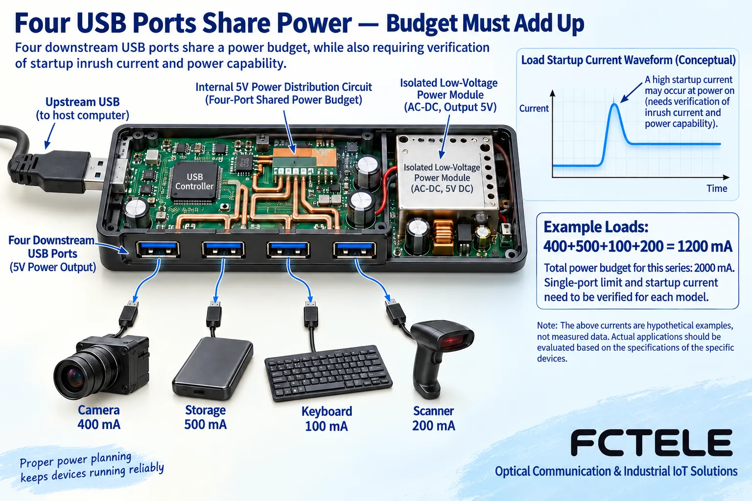
The Feichang series materials list a maximum total current of 2000 mA for the four remote ports. This total allowance cannot be understood as each port being able to output 2000 mA. The per-port limit, device configuration, external power, and startup conditions still need to be confirmed. Fiber does not provide the electrical energy needed by remote devices. The power supply for the receiving device and the allowed peripheral power method should be arranged separately.
For example, assume four peripherals require 400, 500, 100, and 200 mA respectively, with a continuous load totaling 1200 mA; this addition is only used to explain the budget and does not prove that each port or the delivered power supply will certainly meet it. Startup peaks and the allowed load of the power supply also need to be checked. The definitions of the product’s own power consumption, peripheral power, and total power supply capacity should be clarified. You cannot derive that the whole system has sufficient power from one power consumption field.
Distance must satisfy both the optical link and the USB operation
The official website overview and corresponding specification sheet describe a series solution for 10 km single-mode fiber, but the official website technical parameter table has another inconsistent distance field, and old articles also mix in statements from other versions. The supplier should confirm the optical configuration, connectors, and allowed distance according to the exact ordered version. Do not combine these numbers into a maximum distance that guarantees all real-time devices can work.
Optical commissioning also requires checking the fiber type, transmit/receive pairing, and received power window, and accounting for connectors, splices, and engineering margin. USB transactions and application continuity need to be tested separately on the installed cable route. Optical reachability does not mean any peripheral can be used. Do not add ordinary switches or amplifiers into an unsupported dedicated optical link. Use suitable tools for optical port inspection and cleaning, and never look directly into a working fiber core.
Confirm plug-and-play and model options separately
The statement in the materials that no dedicated extender driver is needed should be distinguished from peripheral drivers. Industrial cameras, printers, or manufacturer-specific instruments may still require software. After the operating system recognizes the device, you still need to verify that the application can open the device correctly. Host USB power saving, sleep, and application restart behavior may all affect continuous operation or recovery from abnormalities.
Options such as power supply, installation method, fiber type, and optical interface should be implemented in the delivered model. All options on the web page cannot be treated as default configuration at the same time. When temperature, certification, and special protection conditions lack clear basis, confirmation should be requested. A commercial model should not be written as an industrial model just because the use location is a workshop. Keep the detail page and specification sheet version in the procurement record so that there is a consistent basis for later verification.
Acceptance proves that this combination can work
During commissioning, test in three stages: direct connection, short fiber extension, and installed optical cable, keeping the same host, driver, peripheral, and task mode. Check recognition, actual data, combined operation, and remote load item by item. When problems occur, keep the error information and isolate one variable first. Do not replace all cables, devices, and software at the same time to look for a chance success.
Finally, under the allowed maintenance conditions, test cold start, hot plug, sleep wake-up, fiber break, and power recovery to confirm whether the peripheral is recognized again, whether the application reopens, and whether new data arrives. What is delivered is not only four ports and a kilometer figure, but also port roles, resource budget, test method, success conditions, and recovery steps. After adding devices or upgrading software, re-verify according to these records.
Material note: The principle diagrams have been checked against technical content and are used to explain general mechanisms. They are not physical product photos or measured records. Specific interfaces, modes, and capabilities are subject to the selected model, version, and on-site verification.
Verification materials: Feichang FCP-UT/FCP-UR USB 2.0 optical transceiver details
Feichang FCP-UT/FCP-UR USB 2.0 specification sheet
USB-IF USB 2.0 specification resource entry
Microsoft: USB bandwidth allocation and transfer types
Related technical topics: How to look at USB optical transceiver speed and latency: shared bandwidth, transfer types, and measured acceptance How to judge USB optical transceiver compatibility: host enumeration, endpoint types, and peripheral drivers How to deploy remote peripherals with a USB optical transceiver: host role, on-site power, and fiber break recovery How to plan a conference room video optical transceiver: check HDMI display, USB capture, and IP conferencing separately
Translated from the Chinese technical article. Source first published: 2022-01-06. Source last revised: 2026-10-13T11:52:05+08:00. Read the Chinese source
