


Transmitting video over fiber does not mean image quality will necessarily improve. To judge whether a video optical transceiver can preserve the picture, you should separately check source quality, interface matching, digital receive margin, and output performance. Fiber is good at reducing transmission problems caused by long cables, but it cannot bring back details the camera did not capture, and it cannot automatically repair distortion that entered the device before the signal arrived.
Image quality loss may happen before the fiber
A lens that is out of focus, insufficient light, camera noise, or unsuitable exposure will all affect the source image. What the optical transceiver gets is the signal the camera has already output, not the original scene. If the near-end monitor already cannot see clearly, switching the far end to a more expensive optical module will not necessarily improve it. Establish a source baseline first, then discuss long-distance transmission, so you can avoid blaming everything on the fiber cable.
Analog video may also suffer interference or reflections on short coax. Digital equipment samples changes in input voltage into numeric values, and if noise has already mixed into the effective frequency band, it may be stored along with the signal. Successfully sending these numeric values to the far end over an optical link does not mean the noise has been removed. Reducing new loss added by the transmission section and repairing loss at the source are two different tasks.
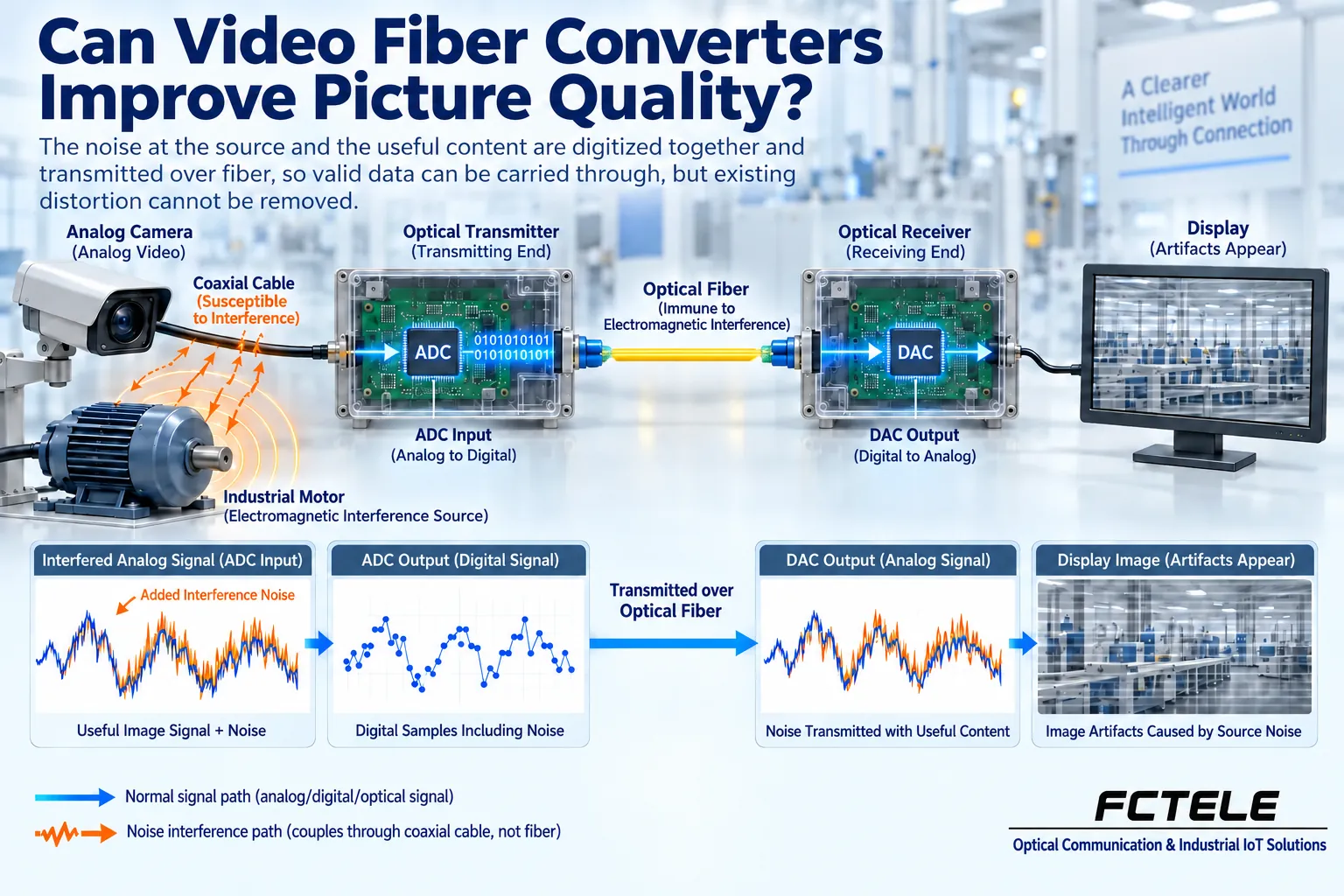
Resolution, frame rate, and transmission rate are not the same
Resolution describes the scale of picture pixels, frame rate describes how many pictures are updated per second, and interface rate describes how fast data is sent over the line. Even when something is called high definition, different frame rates, scanning methods, chroma sampling, and bit depth can mean different data organization. Therefore, when purchasing, you should not just write the words high definition; you should record the actual output format at the source and the formats the receiving device supports.
Setting a higher pixel count in a monitor menu cannot create detail that does not exist in the input. Magnified display, format conversion, and optical transmission each have their own roles; some converters may scale the image, but an ordinary video optical transceiver should not be assumed to have this capability by default. In particular, do not interpret support for one SDI rate as meaning that any resolution and any frame rate can pass through.
Digital reception relies on an effective decision window
The zeros and ones carried by a digital line are still waveforms affected by noise, bandwidth, and clock in a real circuit. The receiving end needs to judge the level at the right moment. If the level difference is too small, or if the edge timing changes too much, the judgment may be wrong. Digital does not automatically remove these physical limits; it only makes regeneration and judgment easier when conditions are met.
In engineering, an eye diagram is used to observe the opening after many symbol waveforms are overlaid. The vertical opening can help understand amplitude decision margin, and the horizontal opening can help understand the time window available for decisions; neither is an image quality score by itself. The figures in this article only explain concepts; they are not measured eye diagrams of any Feichang Technology device, and the size of the opening in the figure cannot be used to derive bit error rate.
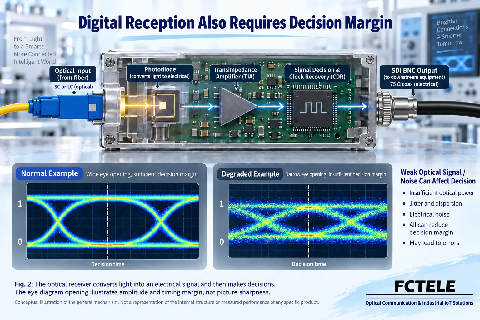
Equalization and clock recovery are not universal repairs
Cable equalization mainly compensates for frequency-related attenuation within a specified range, helping the input edges and amplitude return to a processable state. Clock recovery and retiming mainly handle receive decision timing and the edges that are sent again. If the source data is already wrong, the input exceeds allowed conditions, or the format is simply not compatible, you cannot expect these stages to turn it into correct video.
Whether a device includes retiming, whether it supports bypass, and its operating range should be checked in the actual manual. TI provides technical material on SDI equalization and retiming, but this is only a reference for general mechanisms and cannot be used to infer the chip composition of a particular Feichang Technology model. Seeing a stable picture also does not prove that all input conditions have the same margin; you should test the actual worst-case configuration.
Lossless, compression, and low latency need to be proven separately
A transmission link not performing lossy image compression is not the same conclusion as the whole device producing no signal error at all. Analog sampling has limited precision, a digital link has allowed conditions, and the interface output also has requirements. When a manufacturer describes something as lossless, you need to confirm whether it refers to content encoding, format preservation, or transmission performance under specified conditions; you cannot directly promise that all pictures will never change.
Video delay may come from the sensor, encoding, buffering, format conversion, fiber propagation, and display processing. Increasing optical transmission distance also adds propagation time; there is no zero delay at any distance. If you want to compare two devices, you should keep the video source, format, display, and measurement method as consistent as possible, and you cannot treat the impression from different screens as the delay of the transmission device.
How Feichang Technology products are used for image quality checks
The Feichang Technology FCVH-V1b mini 3G-SDI details list input auto-detection, automatic cable equalization, an extra SDI output, and a signal access indicator. These capabilities can help establish a near-end and far-end comparison and check whether the signal enters the device; an indicator light being on still does not equal complete image quality acceptance, and it cannot extend the equalization range to any coax cable.
This product lists different rates and corresponding cable equalization conditions, which shows that cable length and input rate need to be considered together. When purchasing, provide the actual format, coax type, number of connectors, and optical path conditions, and ask for confirmation of the delivered configuration. Do not write a distance from a product page as the uniform transmission capability of all video optical transceivers.
Establish a repeatable image quality acceptance method
First observe a fixed test pattern, color blocks, fine lines, and moving pictures on a known-good short link, and save the source format. Then, keeping the same source and receiving end, gradually add the formal coax, video optical transceiver, and fiber cable, recording the picture, alarms, lock status, and duration. Change only one item at a time at each stage so you can know where the loss occurs.
Long-duration observation should include normal load and allowed environmental changes, and digital error statistics should be checked according to the device’s capabilities. If there is no statistics function, do not fabricate a zero-error record. If black screens, flicker, or stripes appear, first record the trigger conditions, then replace sections with known-good components; do not blindly increase laser power, and do not touch the inside of equipment while it is powered.
For example, if a workshop video line is normal at the near end but occasionally flickers at the far end, you can first replace the short patch cord, then check connector cleanliness and received power; if stripes already appear at the near end, first check source power, coax, and grounding. This is a hypothetical troubleshooting example, not a verified customer case. Explaining image quality with repeatable results is better than saying transmission is absolutely perfect.
References: TI SDI equalization and retiming reference ; Feichang Technology mini 3G-SDI product . The illustrations are general principle diagrams and do not represent measured waveforms or internal structure.
Translated from the Chinese technical article. Source first published: 2024-01-08. Source last revised: 2026-10-13T13:52:20+08:00. Read the Chinese source
