


First identify the camera output, then talk about multi-service
A multi-service video optical transceiver is used to carry the video it supports plus additional channels such as audio, serial ports and telephone. Its capability comes from the specific interfaces and internal transmission design, not from automatically turning all image and control signals into one standard. Analog composite video, SDI digital video, HDMI display interfaces and IP camera network services need different receiving and output conditions, and cannot be freely interchanged just because they are all called video.
Before design, list the source devices, interfaces, video formats, quantities, directions and receiving devices. The BNC of an old surveillance camera may output analog video, or it may be a digital interface such as SDI; the shape of the connector cannot replace judgment of the signal standard. What the user wants to keep is the complete service, not just one optical cable, so it is also necessary to check pan-tilt control, audio, power and recording-end support.
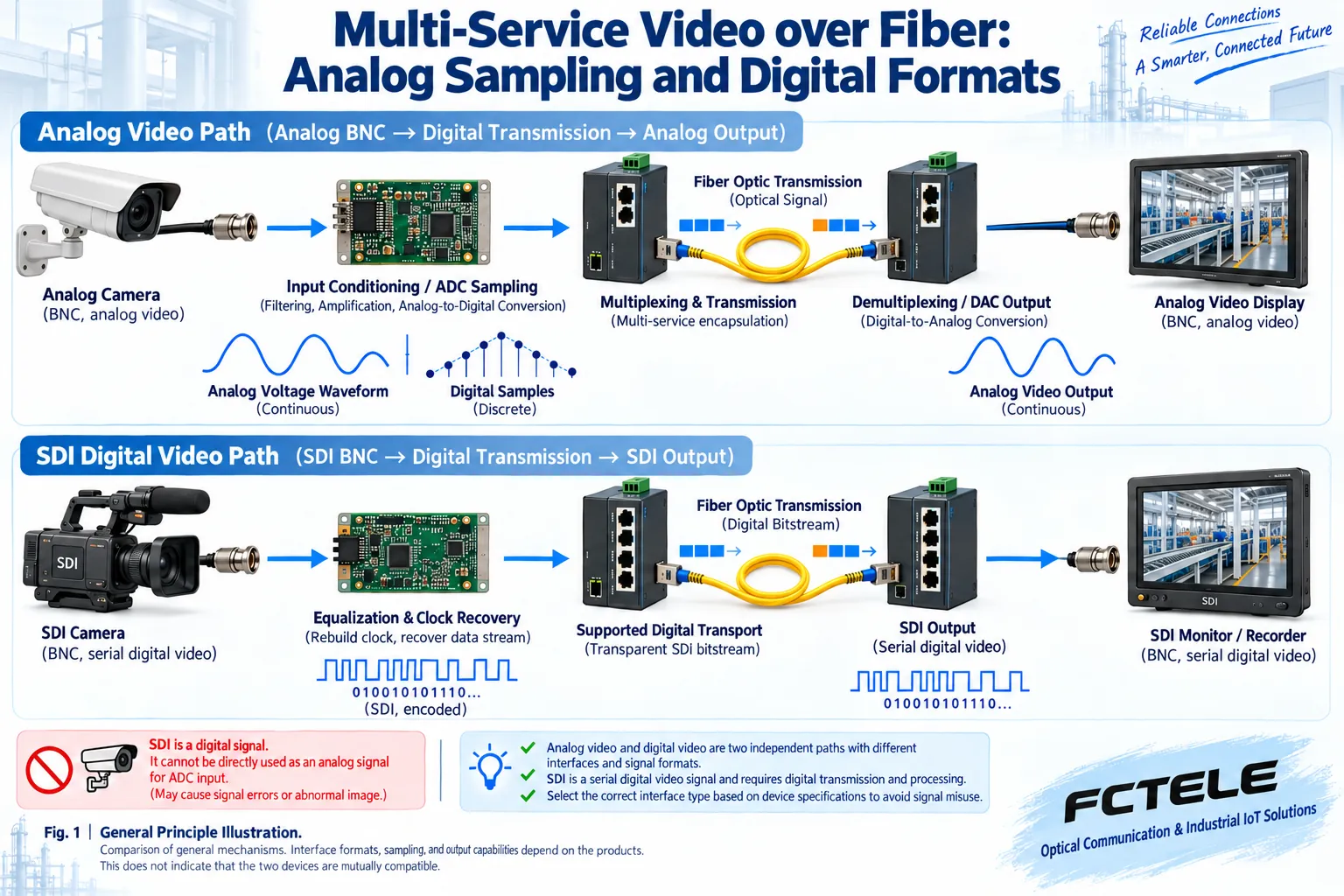
Analog modulation and digital sampling are different paths
In a corresponding analog optical transmission design, the input video can directly affect the light emission intensity, or it can first modulate an electrical carrier and then drive the optical transmitter; the receiving end recovers the corresponding analog signal through matched detection and demodulation. The specific amplitude modulation, frequency modulation and line processing depend on the design. The result of frequency demodulation cannot be written as necessarily being digital video, and the linearity and noise performance of all analog devices cannot be treated as identical.
A digital video optical transceiver, however, can first sample the analog input into digital values: an analog-to-digital converter ADC reads the amplitude at specified moments, and after quantization and encoding forms data, which is then organized into the optical transmission channel. After matched recovery at the far end, the corresponding analog video is output through processing such as a digital-to-analog converter DAC. This path may still connect to an analog camera externally; using digital data internally does not turn the camera interface into HDMI.
The TI TVP5150AM1 document provides a chip example of converting analog baseband video into digital component data, for understanding the sampling and decoding stages; it does not prove that Feichang Technology equipment uses that chip. The number of sampling bits, timing, input standard and output format all have conditions. The performance of an entire optical transceiver cannot be derived from one chip parameter, and digitization cannot be equated with automatic compression or improvement of the original image quality.
Why does SDI input still need clock recovery?
The SDI interface already transmits digital video in a specified serial manner. Receiving and processing may involve coaxial equalization, data and clock recovery, and format checking, before entering the transport path supported by the device. Equalization is used to compensate for certain line effects, and clock recovery helps read the data at the appropriate moments; these are different from performing ADC sampling on analog composite video again.
Semtech’s SDI receiver documentation shows the corresponding standard processing and data integrity checking mechanisms, but it cannot prove that all optical transceivers have the same capability. HDMI also involves a display link and related auxiliary interaction, while IP cameras involve network protocols and applications. When a product lists several interfaces at the same time, it should be confirmed whether they are each transported separately, clearly format-converted, or optional; an interface list cannot be treated as proof of arbitrary bidirectional conversion.
How do multiple video channels enter the same optical channel?
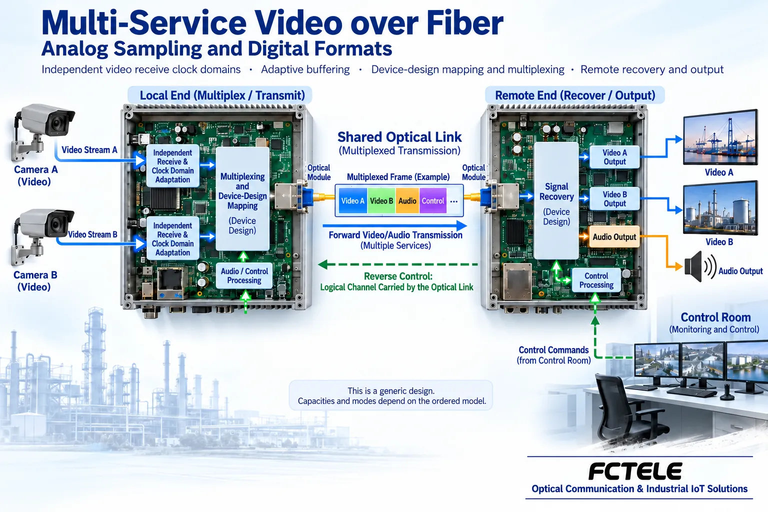
Each input channel may have its own rate, timing and phase. It needs to go through corresponding receiving and adaptation first, and then be carried together according to the device’s designed mapping, multiplexing or switching method. Data from different sources cannot simply have their bit streams concatenated to obtain a recoverable signal; the receiving end also needs to know which part belongs to which channel, and how to recover the timing and format required by the original interface.
Buffering can handle limited short-term timing differences, but when continuous input exceeds the output capacity, data accumulation will still increase. Whether clock adaptation, frame synchronization, specified stuffing or other methods can be used depends on the service and design; it cannot be announced across the board, as in older articles, that all asynchronous high-definition video cannot use FIFO or rate adjustment, nor can it be claimed in reverse that any format can be losslessly mixed.
A complete format includes the picture, synchronization and corresponding auxiliary information. Transporting only the active picture and transporting a complete transparent interface are different schemes, and may place different requirements on reconstruction at the receiving end and on additional services. When purchasing, state whether embedded audio, auxiliary data and all format modes are retained, and check compatibility at both ends. Looking only at resolution or the name “high definition” is not enough to determine line capacity and interoperability.
What kind of needs is the Feichang FCV-V4T/R suitable for?
The Feichang product 218 FCV-V4T/R page lists 4 video channels and a modular multi-service configuration direction, and audio, data, telephone, E1, Ethernet, contact closure and other service combinations can be selected as needed. Here it should be understood according to the product’s specified analog video interfaces and ordering configuration, and it should not be directly treated as a device supporting arbitrary SDI or HDMI conversion.
Its configuration method is suitable for selecting additional channels according to the actual signal list. Video usually goes from the site to the center, pan-tilt commands may use a reverse serial port, and audio has its own level and direction. The optional combinations listed on the page are not the default full set of every device; the channels, quantities and interface versions at both ends need to be clarified, and then desktop or rack installation and power supply confirmed. Model capabilities and the general mechanisms above should be checked separately; modularity cannot be used to assume arbitrary hot swapping.
Conferences, teaching and surveillance cannot be completed by the optical transceiver alone
Optical transmission can extend a clear display, video or peripheral link, but it does not automatically become an internet conference, remote teaching or medical consultation platform. Cross-location collaboration also requires suitable applications, networks, audio and video equipment and permissions; the fact that the device can send signals does not mean it already has calling, recording, sharing or service management functions. Application scenarios may be the same, but the technical objects may still be different.
In surveillance solutions, analog video optical transceivers and IP switching networks should also be distinguished. The latter processes Ethernet frames and does not automatically sample analog cameras on the optical uplink; the former recovers video according to compatible interfaces. When network recording, digital display or access with different standards is required, every conversion point should be clearly marked, to avoid handing the wrong interface to the name “multi-service” to solve.
From single channel to concurrent and recovery acceptance
First use a known-good source and receiving device to establish a short optical path, and confirm the format, direction, output and optical interface pairing. Verify video synchronization, audio, control and other services channel by channel, then add the formal line and run all planned channels at the same time, observing shared resources and application continuity. Test records should include model, firmware, format, modules and service load, not just a photo with a picture.
In an approved window, verify disconnection, power recovery and applicable protection, and record which services are interrupted and when they recover. When all services disappear at the same time, check the common power supply and optical path; when one channel is abnormal, also check the corresponding interface, format and configuration; a single symptom is not enough to determine the root cause. Optical budget, fiber type, wavelength, cleaning and grounding should be implemented according to the accompanying documentation; the mechanisms in the figures cannot replace physical wiring. Only by understanding separate reception, adaptation, multiplexing and recovery can you judge which signals a multi-service optical transceiver can truly carry.
Documentation note: The principle diagrams are used to explain general mechanisms, not product photos or measured records. Specific interfaces, modes and capabilities are subject to the selected model, version and on-site verification.
Verification materials: TI TVP5150AM1 analog video sampling and decoding
Semtech GS2971A SDI receiving and processing
Feichang FCV-V4T/R multi-service video optical transceiver
Feichang digital video optical transceiver classification
Related technical topics: How GMRP manages Layer 2 multicast: MAC registration, leaving and differences from IGMP How industrial switch ACL works: rule matching, binding direction and access acceptance How to configure DHCP Snooping: trusted ports, binding table and address acquisition troubleshooting How switch loop detection works: probe return, port handling and controlled recovery
Translated from the Chinese technical article. Source first published: 2022-06-17. Source last revised: 2026-10-13. Read the Chinese source
