


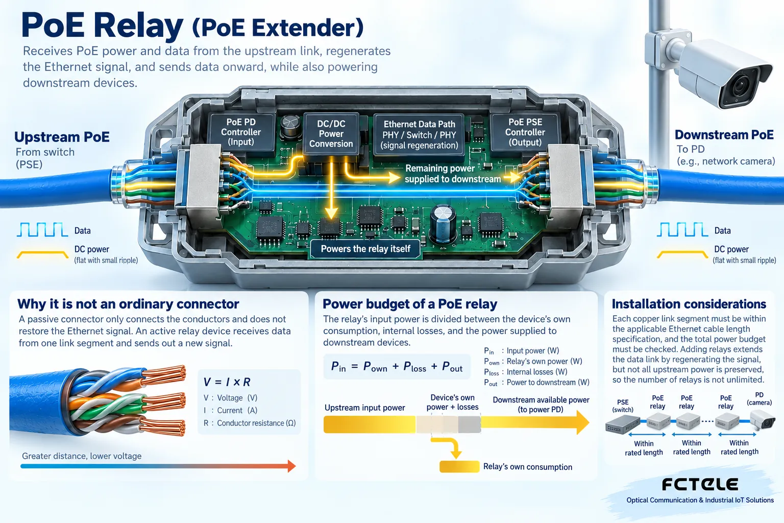
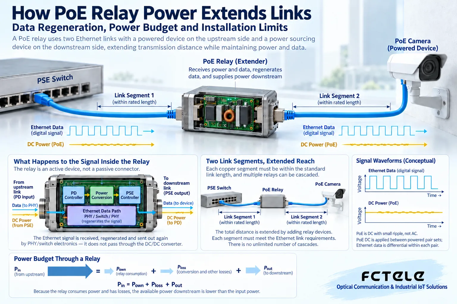
A PoE relay device receives upstream power in the middle of a link, resends Ethernet data, and may supply power to downstream devices. It also consumes electrical energy, so extending data distance does not equal keeping all upstream power, and it does not mean the number of relays can be increased without limit. Each data link segment and the complete power budget must be checked separately.
Why it is not an ordinary connector
A passive connector only connects conductors and does not restore the Ethernet signal. An active relay device receives data from one link segment and sends out a new signal from the other end; whether it has multi-port switching, PoE passthrough, or independent power supply capability depends on the specific product. Standard channels for common copper Ethernet are usually designed for 100 meters. A relay can form a new link segment, but each segment still needs to meet the corresponding interface, cable, and cabling requirements. The rate and distance of special long-distance modes cannot be directly treated as promises for ordinary modes.
Power has losses all the way from the inlet to the camera
The power provided by the upstream PSE passes through cable loss and reaches the relay device; the relay first satisfies its own operation, then sends the allowed remaining power downstream. The downstream cable will continue to lose more. Therefore, the PSE power budget, relay input rating, self-consumption, output capability, and camera maximum demand should be checked, not just the nominal wattage of the power supply switch. The peak when the camera infrared, heater, or pan-tilt starts may also be higher than the consumption shown in daily use.
Putting two relays in series costs more than just one extra box
Each additional unit adds self-consumption, cable loss, connectors, and failure points. The series connection capability, supported power levels, and allowed topology need to be clearly stated by the product; reliability cannot be assumed just by trying to plug it in. A multi-port relay also involves the total budget of all output ports: each port supporting a certain power does not mean all can be fully loaded at the same time. When longer distance and high power are needed, nearby power, fiber plus remote power, and other solutions can be compared, rather than only stacking copper relays.
Check direction and standard first for on-site wiring
Confirm which port connects to the upstream PoE input, which port provides downstream output, and whether it is compatible with the IEEE standard power sourcing and powered device mechanism. The same connector shape does not mean input and output can be exchanged freely, nor does it mean non-standard fixed voltage can be safely mixed. Outdoor installation also requires waterproofing, heat dissipation, grounding, and surge measures; improper installation of waterproof connectors will increase contact resistance and reliability risk. Cable conductors, connection quality, and ambient temperature all affect voltage drop and heat generation.
Acceptance should look at both video and power stability
Record the negotiated rate, error count, and continuous transmission performance of each segment separately, and test power supply under the terminal’s maximum load condition. A camera light turning on or a single Ping is not enough to judge completion. Simulate power-off restart and load changes, and check whether there are repeated restarts, speed drops, or alarms. The procurement list should state cable conditions, terminal requirements, and relay stages, and let the supplier confirm the complete solution, rather than only asking for a distance number.
Example: the camera works normally during the day but repeatedly restarts at night
This phenomenon may be related to the load increase after infrared turns on, but it cannot be characterized without measurement. First check the camera’s maximum nighttime demand, the relay output limit, and the upstream allocation, then test the voltage drop, temperature, and contact condition of the cables and connectors before and after the relay. Power supply failure, terminal abnormality, and data link problems should also be ruled out. If the budget is insufficient, prioritize adjusting the power architecture or reducing relays, rather than treating the camera’s minimum power consumption as a permanent requirement. Only by recording continuous operation results under the worst conditions can the solution be proven stable.
Principle reference:Official technical materials. The structural diagrams in this article do not represent specific product specifications; model selection should check the model manual.
Translated from the Chinese technical article. Source first published: 2022-02-10. Source last revised: 2026-10-13T20:54:09+08:00. Read the Chinese source
