


Multiple serial servers can connect to the same listening port on a central server in TCP Client mode. The key is not to open a separate public port for each device, but whether the central program can manage multiple connections at the same time, identify which device each connection corresponds to, and send and receive data correctly according to the protocol. A successful connection, correct device identity, and normal serial service are three conditions that each need to be verified separately.
1. First distinguish two easily confused scenarios
This article discusses “multiple on-site serial servers connecting to one central program.” Each serial server sends the data of its own serial device to the center, and the center then sends requests down along the corresponding connection. For example, three independent power distribution cabinets each have one serial server, and the center needs to know which cabinet a certain reading came from and send control commands back to the correct location.
Another scenario is “multiple computers accessing the same serial server.” This involves whether the same serial device can be operated by multiple masters at the same time, which may cause request conflicts and unclear response ownership. Supporting multiple TCP connections does not mean automatically supporting safe multi-master control. The two scenarios differ in device direction, number of sessions, and scheduling issues, and cannot be covered by simply saying “automatic polling is enough.”
2. Why one port can connect multiple devices
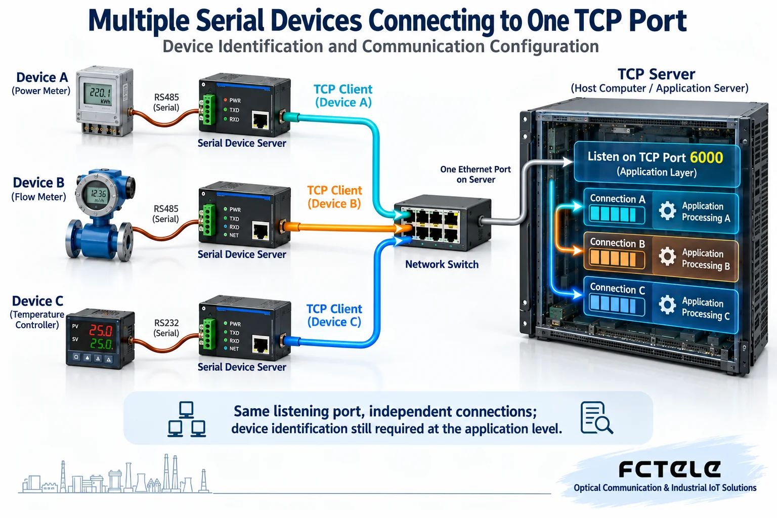
A TCP port can be understood as the service entrance of the central program, but it is not a physical jack that can only be occupied by one device. The program listens on a specified address and port. After accepting a connection, the operating system provides an independent connected socket for that session. A socket is the interface through which a program reads and writes network data; the original listening entrance continues to wait for other devices to connect.
In a network, one TCP connection is distinguished by the combination of the IP addresses and ports of both sides. Even if all devices access the same port on the center, their source addresses or source ports can be different. The center should separately store the receive buffer, state, and processing task for each connection, and must not mix bytes received from different connections directly into the same parsing queue.
Suppose the center listens on port 6000, and devices A, B, and C actively connect separately. These are three independent sessions, not three devices taking turns occupying the same session. 6000 is only an example, not a recommended fixed value. The actual number of connections is limited by the central software, device firmware, system resources, and network policies, and “one port” cannot be used to infer unlimited device capacity.
3. Once there is a connection, why device identity still needs to be identified
A connection can tell the center “which session this batch of bytes entered from,” but it does not necessarily tell it “which power distribution cabinet this is.” Public network access may pass through NAT, meaning the router rewrites network addresses and ports; multiple devices can appear with the same exit IP. After a disconnection and reconnection, the source port may also change, so a temporary source port cannot be permanently used as a device number.
Identity mapping can use verified fixed network configuration, or registration messages, station numbers, and authentication information defined in the application protocol. Which one to choose depends on what the terminal, serial server, and central software actually support. A transparent serial server usually only carries bytes, and it should not be assumed that it will automatically insert a unique identity into the data; if the registration packet function is needed, the actual model and firmware documentation must be checked.
The serial slave address is also not necessarily unique in the entire system. For example, if the meters in three independent cabinets are all set to station number 1, as long as they belong to three connections respectively, the center can distinguish them by “confirmed cabinet number plus station number.” But if the bytes are mixed together and only station number 1 is seen, it is easy to mistake the device. A station number is an address within the protocol and is not equal to the globally unique identity of the entire serial server.
After a connection is established, verify the identity first, then allow service operations. When the same identity comes online repeatedly, it must be made clear whether to reject the new connection, replace the old connection, or handle it according to a redundancy design, and two connections must not quietly compete for the same device record. Self-reported identity is also not equal to trusted authentication, and a formal network should also combine authorization and access control.
4. Why transparent transmission needs protocol-based framing
The serial server first receives serial bytes, temporarily stores them in a buffer, and then sends them over Ethernet; in the reverse direction, it also delivers network bytes to the serial output. The baud rate, data bits, parity bit, stop bits, and electrical interface must still match the on-site terminal. TCP is responsible for ordered byte transmission and does not automatically understand meter registers, device numbers, or control commands.
TCP is a byte stream, and one read by the center may get half a message or may get two messages. The application should accumulate and parse according to the protocol’s length, delimiter, checksum, or state rules, and then process the complete message. ABC and DEF in the figure are only byte examples for easier understanding, not actual Modbus frames; one network read cannot be used as the message boundary for all protocols.
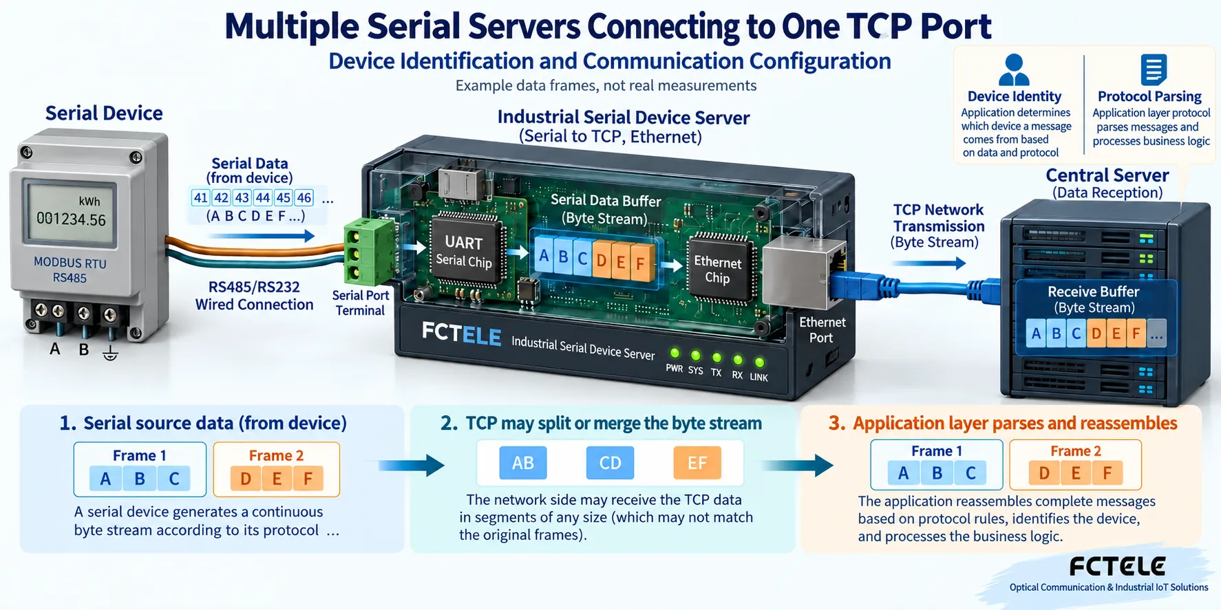
Requests and replies must also be managed by connection. When the center sends a request to connection A, it must not treat data received on connection B as A’s reply. When multiple slaves on the same RS485 bus need to be read, requests should be scheduled according to the protocol and device processing time, and the next operation should be performed only after confirming the response or timeout. Packing wait, network delay, and serial transmission time all affect the timeout, and parameters should be tested item by item rather than setting all wait values to zero.
5. During configuration, check section by section along the data path
First configure the listening address and service port of the central program, confirm that it can accept multiple connections at the same time, and parse data independently for each connection. Then set each on-site serial server to TCP Client and fill in the center address and target port. Do not mistake the management web page port for the service port, and do not set both the on-site end and the center end to wait for connections.
Then check routing and access policies. If the center is on an internal network, public network devices cannot access it using only the center’s private address; a controlled VPN, private network, or approved mapping scheme is required. Opening a port is only part of the network path and will not automatically complete device identity, protocol conversion, or application authorization. The firewall should allow only necessary sources and services, and the management interface should not be exposed casually along with the service port.
Finally, confirm the serial wiring and parameters, establish a minimal system with one device, verify the request and reply content, and then add devices. An older article proposed that virtual serial ports and a serial assistant could solve all multi-device access, but this is not universal: the virtual COM driver, central program, and device mode must be compatible with each other; a self-developed TCP program also needs to complete connection management and protocol parsing.
6. What to test for disconnection reconnection and acceptance
After the network disconnects, the old session must not occupy the service identity forever; reconnection should re-verify the identity and decide according to the protocol how to handle unfinished requests. Reliable TCP transmission does not mean that a service command is executed exactly once before and after a disconnection. For operations such as start/stop and reset, they must not be sent repeatedly without condition just because of a timeout; state queries, transaction numbers, or mechanisms supported by the device should be used to avoid repeated execution.
For acceptance, different devices can be made to return distinguishable data, and the center display can be confirmed one by one to match the actual device; then connect them at the same time and test whether data is crossed or responses are misidentified. Then disconnect one of them and check whether the other devices can continue working and whether the reconnected device returns to the correct record. The number of connections, serial send and receive counts, timeouts, and buffer conditions should also be recorded, and continuous operation and peak load should be tested.
7. Check the actual working mode when selecting devices
The official website details of the Feichang FCT-1500 series list TCP Server/Client, virtual serial port drivers, and different RS232/422/485 configurations, and can be used to network distributed serial devices. Choosing TCP Client helps on-site devices actively connect to the center; however, center identity mapping and request scheduling still belong to the overall solution. The per-channel multi-session capability listed on the official website cannot replace central software capacity verification, and the specific interface, mode, and firmware need to be checked according to the ordered model.
Transparent TCP access and Modbus RTU to TCP conversion should also be confirmed separately. When protocol conversion is needed, choose and enable the mode that is actually supported, and do not directly treat transparent serial bytes as Modbus TCP messages. For general troubleshooting, refer to 2295; this article keeps the independent issue of multi-device aggregation and avoids repeatedly listing general content such as device not found and COM port cannot be opened.
References:IETF RFC 9293 TCP specification;Linux accept connection interface documentation;Feichang FCT-1500 series details;Serial server troubleshooting. The principle diagrams are general principle illustrations, explain general mechanisms, and do not represent actual products, measured results, or promised connection capacity.
Translated from the Chinese technical article. Source first published: 2020-08-17. Source last revised: 2026-10-13T20:24:48+08:00. Read the Chinese source
