


A serial server solves “how to connect old instruments to the network,” while a switch solves “how to interconnect multiple Ethernet devices.” The former moves bytes between serial signals and network data; the latter selects forwarding ports based on Ethernet frame addresses. They are often used together, but an ordinary switch will not automatically turn RS485 into a network port, and a serial server cannot replace all switch functions just because it has a few network ports.
1. First look at what the terminal outputs, not the shape of the box
Suppose an instrument only has an RS232 or RS485 interface, and the computer acquisition system is on Ethernet. The instrument sends serial signals arranged by baud rate, while an ordinary switch network port expects Ethernet signals and frame formats. Even if you make a connector adapter cable, it cannot make these two sets of electrical and communication rules understand each other. At this point, you need a serial server that matches the instrument interface, or a gateway that explicitly supports the corresponding protocol.
If the terminal already has an Ethernet port and the application can access it using the network protocol it supports, usually you can just connect the terminal to a switch without going through a serial server. DB9, terminal blocks, or RJ45 are only connection forms; you cannot infer the internal signal from the shape alone. Some consoles also use an RJ45 shell but are not Ethernet ports; plugging in by mistake can cause communication failure and even electrical risk; you should first check both manuals.
2. How a serial server moves bytes internally
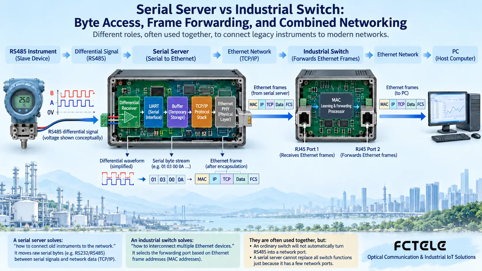
Take an instrument sending data to a computer as an example. The serial transceiver circuit first receives the electrical signal. The UART, or universal asynchronous receiver/transmitter, recovers bytes according to baud rate, data bits, parity, and stop bits. The bytes are temporarily stored in a limited buffer, and the network protocol stack then puts them into the corresponding network transmission and sends them out from the Ethernet interface. When the computer requests data from the instrument, the direction is reversed: network bytes are queued through the buffer, then sent bit by bit to the instrument by the UART and serial circuit.
Fast network speed does not mean serial sending is also fast. A low-speed instrument still works at its own format, and the buffer can only absorb a certain speed difference, not store indefinitely. Transparent transmission usually preserves application bytes and is not responsible for understanding the meaning of each register. RS485 is an electrical interface, Modbus RTU is a message rule, and TCP is a network transmission mechanism; having RS485 and TCP does not automatically prove support for Modbus RTU to Modbus TCP conversion. When conversion is needed, you should clearly check the gateway mode.
3. How a switch decides which port to send out from
After an ordinary Layer 2 Ethernet switch receives a frame, it learns the association between the source MAC address and the incoming port within the corresponding network scope. MAC can be understood as the identifier used by an Ethernet interface for frame addressing, not an instrument station number. When subsequent frames are received, the switch looks up the port associated with the destination MAC and sends the frame in the corresponding direction; for unknown destinations, broadcasts, and similar cases, it forwards to allowed ports according to network rules, not always to just one port every time.
So a switch mainly forwards frames between network nodes. It does not “control other computers” for the computer, nor does it automatically execute instrument commands. A managed switch may provide VLAN, priority, port statistics, and redundancy mechanisms, but the specific capabilities depend on the model. A Layer 3 switch may also support routing, which is different from ordinary Layer 2 forwarding. You cannot call all switches routers, and you should not imagine every switch as having one fixed “main network port”; an uplink port is a role in the topology, not a uniform physical rule.
4. How the two types of devices combine in networking
A common structure is “instrument—serial server—switch—acquisition computer.” When multiple instruments are scattered on site, they can each connect to the corresponding serial server, and then the Ethernet ports of these servers are aggregated into a switch. The switch provides the interconnection path. The host computer accesses according to each server’s IP, service port, and working mode, and finally the application distinguishes instrument identities and parses replies. You cannot just plug cables into devices and assume the business protocol is already interoperable.
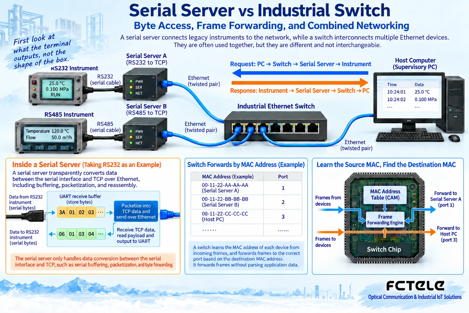
The computer does not necessarily need a physical serial port. When software supports a Socket network interface, it can connect to the server’s address and listening port; when old software only recognizes COM ports, a compatible virtual serial port driver may be needed. The driver maps local COM operations to the network device, but control lines, exclusivity, timeouts, and reconnection behavior need testing, and you cannot promise that all old software is completely equivalent. Multiple computers connecting at the same time also does not mean they can send commands to one RS485 bus simultaneously without coordination.
5. How to view a serial server with switching functions
The two types of functions can be integrated in the same device. The Feichang Technology FCT-1500 series 2855 details list 1–4 channels of RS232/422/485 combined with switched 2-port 100M electrical ports and 1-port 100M optical port. On site, you can connect serial terminals according to the ordered configuration and use the corresponding network interfaces for interconnection or to extend the media path. The details also list capabilities such as virtual serial port and RTU/TCP conversion; these correspond to software access and protocol conversion issues respectively, not results naturally included with ordinary switch forwarding.
An integrated solution can reduce the number of devices, but you should check the actual use of electrical and optical ports, the number and mode of serial ports, and evaluate which nodes will be affected at the same time if power is lost. You cannot infer from “with switching” that it supports any VLAN, ring protocol, or Layer 3 routing, and even less can you generalize optical port capability into unlimited transmission distance. Optical modules, fiber, link budget, and switching capability still need to be checked in the corresponding configuration. Centralized control must also preserve permission boundaries and not directly expose management and service ports to the public network.
6. Separate selection and troubleshooting into two lines
When choosing a serial server, first check the RS232/422/485 standard, two-wire or four-wire, terminals, electrical isolation, baud rate, flow control, protocol, and software method, then look at the network role and business session limits. When choosing a switch, check the number and speed of Ethernet ports, media, topology, management, and redundancy requirements. The industrial environment specifications of the two should also be confirmed separately; “industrial grade” does not mean all models have the same temperature, certification, or reliability guarantees.
If network connection fails, check power, network cable, IP, VLAN, routing, ports, and access policies; if a TCP connection is established but the instrument does not respond, then check serial wiring, parameters, station number, and request format. A web page opening only means the management service is reachable, and a link light being on also provides only limited evidence. If bytes can be received but parsing fails, you should save the raw message and check protocol boundaries and checksums, rather than just replacing the switch. TCP is an ordered byte stream; one read may get half a message or multiple messages, and the application still needs framing.
For acceptance, first use a single terminal and a known read-only request to establish a baseline, then gradually connect all nodes and test complete replies, latency, and recovery under expected load. Schedule tests such as network disconnection and restart during authorized maintenance windows, and control commands need to prevent duplicate actions caused by timeout retries. Save model, firmware, configuration, wiring, and normal logs so maintenance personnel can explain whether the problem occurs at the network forwarding, byte access, or business understanding layer.
For specific operations, you can continue to read TCP server connection tutorial and serial server usage guide. In one sentence: a switch connects Ethernet nodes, and a serial server connects serial terminals to the network; they can cooperate or be integrated, but they still have different technical responsibilities.
References:Feichang Technology serial server category;FCT-1500 series 2855 details;IETF RFC 9293: TCP byte stream. Integrated 2095 and 2083, corrected expressions such as “switch controls PC.” The schematic diagrams are general mechanism illustrations and do not represent actual products or measured results; specific capabilities are subject to the ordered model and manual.
Translated from the Chinese technical article. Source first published: 2022-05-06. Source last revised: 2026-10-13T19:15:07+08:00. Read the Chinese source
