


The optical modem handles access to the optical network, the router connects different IP networks, and the switch organizes port communication within a local area network. This is the starting point for understanding the three, but one device may integrate multiple functions: an optical modem with routing can also serve as a home gateway, and a home router often has built-in switching and wireless access. To judge wiring and faults, you should look at the current function and configuration, and you cannot understand the three names as boxes that never overlap.
What network the optical modem accesses is not arbitrary optical-to-electrical conversion.
A home broadband optical modem is usually an ONU or ONT in a PON network. The central office OLT, the passive optical distribution network, and the user terminal work together to complete optical access and service bearing. In addition to transmitting and receiving light, the terminal must also follow the corresponding access protocol and registration and management processes; you cannot connect an ordinary Ethernet fiber transceiver to an operator’s PON line and get broadband.
Normal optical access and being able to go online are not the same state. The operator may also need to configure services, authentication, or address acquisition. The purpose of the terminal’s LAN, telephone, or IPTV ports depends on the service and configuration; not all ports provide the same service when a computer is plugged in. After seeing the PON indicator status, you should judge according to the device manual and the operator’s instructions, and you cannot summarize a single light being on as the whole network being normal.
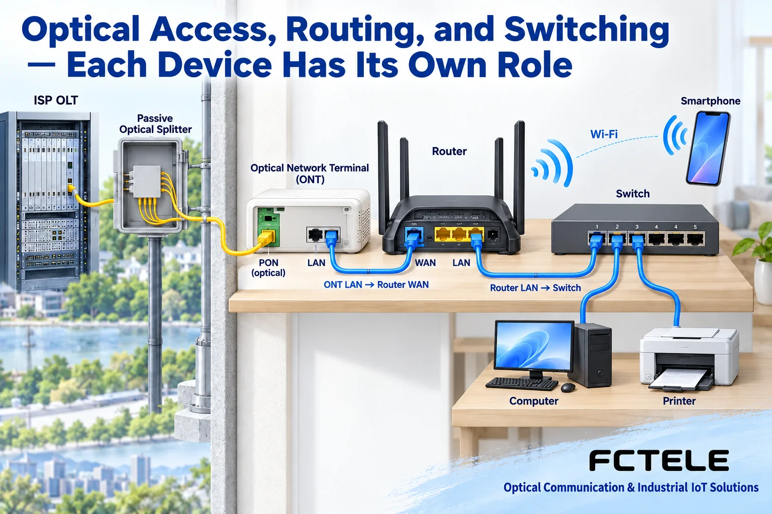
A router does not just send Wi-Fi, and WAN is not necessarily used for dialing.
A router decides which network to send data to based on the destination IP address and routing rules. Home devices often call the interface facing the upper-level network WAN, and the interface facing internal terminals LAN; actual ports may also support custom roles. The WAN connection method can be PPPoE, automatic address acquisition, or a static address, etc., and not all broadband requires dialing. Before connecting, first confirm the service delivery method.
Home routers also often integrate address allocation, NAT, firewall, and Wi-Fi. DHCP helps terminals obtain address parameters, but getting an address does not prove that the external network is already connected; NAT is an address translation function, and it is not a mechanism that all routing forwarding must use. A wireless access point is mainly responsible for wireless terminal access, and you cannot conclude that it must handle operator authentication and routing just because it has an antenna.
How a switch helps terminals communicate
A common Layer 2 switch learns the correspondence between source MAC addresses and ports, and then sends frames out based on the destination MAC and forwarding rules. It is usually used to add LAN access ports or connect other network devices. When two computers are in the same appropriate subnet and VLAN, communication can be completed through the switch, and every frame does not need to go all the way to the router WAN and back.
When the destination is another IP network, the terminal usually hands the traffic to the default gateway, and a device with routing functions continues to forward it. A Layer 3 switch can also perform routing according to configuration, so “a switch is just a router that cannot dial” is not an accurate explanation. Layer 2 switching, routing, broadband authentication, and wireless access each answer different questions; whether they are placed in the same machine does not change the difference between these tasks.
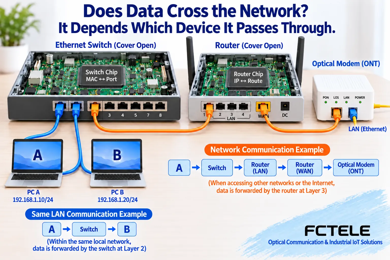
Two common wiring methods: first determine who serves as the home gateway.
The first is a bridged optical modem connected to an independent router: the optical modem provides the corresponding service access to the backend, and the router completes authentication or address acquisition according to the operator’s requirements and manages the home LAN. A switch can be connected to the router’s LAN side to expand ports. The second is when the optical modem is already in routing mode: it may already handle broadband access, routing, and address allocation, and a backend switch can be connected to its available LAN port according to configuration, and it is not necessarily required to add another independent router.
Therefore, the absolute statement in the original text that “a switch cannot be directly connected to an optical modem” needs to be removed. Whether it can be connected depends on the optical modem’s services and gateway role. If the backend wireless device also enables routing, two layers of NAT may be formed, affecting some remote access or applications; if it is used as an AP or bridge, then it is another configuration. Back up parameters before adjustment, and confirm with the operator; do not blindly change to bridge mode or restore factory settings for experimentation.
Feichang Technology industrial ONU example: functions may be integrated, but the environment still needs to be checked.
Feichang Technology FCX-8001 industrial ONU The page lists PON access, 4 gigabit electrical ports and routing mode configuration, as well as optional PoE. This shows that PON access and some gateway functions can be integrated, but it cannot be inferred from this that all optical modems have the same functions, and it certainly cannot be assumed by default that it is suitable for any operator line. Central office compatibility, service authorization, firmware, and specific options still must be confirmed.
This model is aimed at industrial deployment, and it cannot be directly equated with a home gateway with Wi-Fi, nor can optional PoE be treated as standard on all ports. If the project needs to supply power to cameras, the delivery configuration and power arrangement should be checked; if it is only for home wireless coverage, then access, routing, and wireless layout need to be evaluated separately. Including an industrial ONU in the equipment list will not automatically solve the wireless signal problem in a room.
When internet access is abnormal, judge segment by segment along the path.
First check the optical modem’s power supply and the optical alarm, registration, and service status defined in the manual, and keep the time and symptoms; for optical layer or registration abnormalities, contact the operator first. If the access status is normal, then check the router WAN address and service method, and then check the computer address, gateway, and DNS. DNS is responsible for resolving domain names to addresses, and failure to access a domain name does not necessarily mean the optical path is down.
When wired communication is normal but wireless is slow, continue checking coverage, interference, and terminal capabilities; when the LAN can access devices but the external network is unreachable, then investigate the gateway, authentication, or upstream. Speed tests are also affected by the plan, port negotiation, routing performance, wireless link, and test server, and you cannot just count antennas or vaguely write “the router cannot handle twenty computers.” Recording segment by segment can avoid attributing all faults to the same box.
During maintenance, do not look directly into the optical port or forcibly bend the pigtail; do not treat interfaces marked for other services as general-purpose LAN. After the device role, port purpose, current configuration, and test results are written clearly, the next person troubleshooting can review along the same data path.
Reference for Layer 2 switching and IP routing responsibilities Cisco routing description; the functional boundaries are subject to the actual model and service configuration.
Translated from the Chinese technical article. Source first published: 2020-06-12. Source last revised: 2026-10-13T18:44:52+08:00. Read the Chinese source
