


When asking for the price of an industrial fiber switch, you cannot just say “I want one that covers a few kilometers.” The switch itself, the optical modules at both ends, the fiber cores, the connectors, the power supply, and the installation work all need to be considered together. In particular, an SFP slot does not mean an optical module is already installed, and the module’s rated distance does not mean it will work reliably on any line. Only by explaining the optical link clearly can you avoid the situation where the bare unit price is cheap but the link does not work after installation.
1. What exactly are you buying in an optical port quote?
Fixed optical port transceivers are usually integrated into the device; SFP is a small pluggable transceiver module, and the slot provides its connection to the switch. If the quote only includes SFP slots, you still need to confirm whether modules are included and whether the quantity is sufficient. A link connecting two ends usually requires checking the transceivers at both ends; you cannot just buy a module for your end and assume that any optical port at the far end will be compatible. The number of optical ports and the number of electrical ports should also be listed separately.
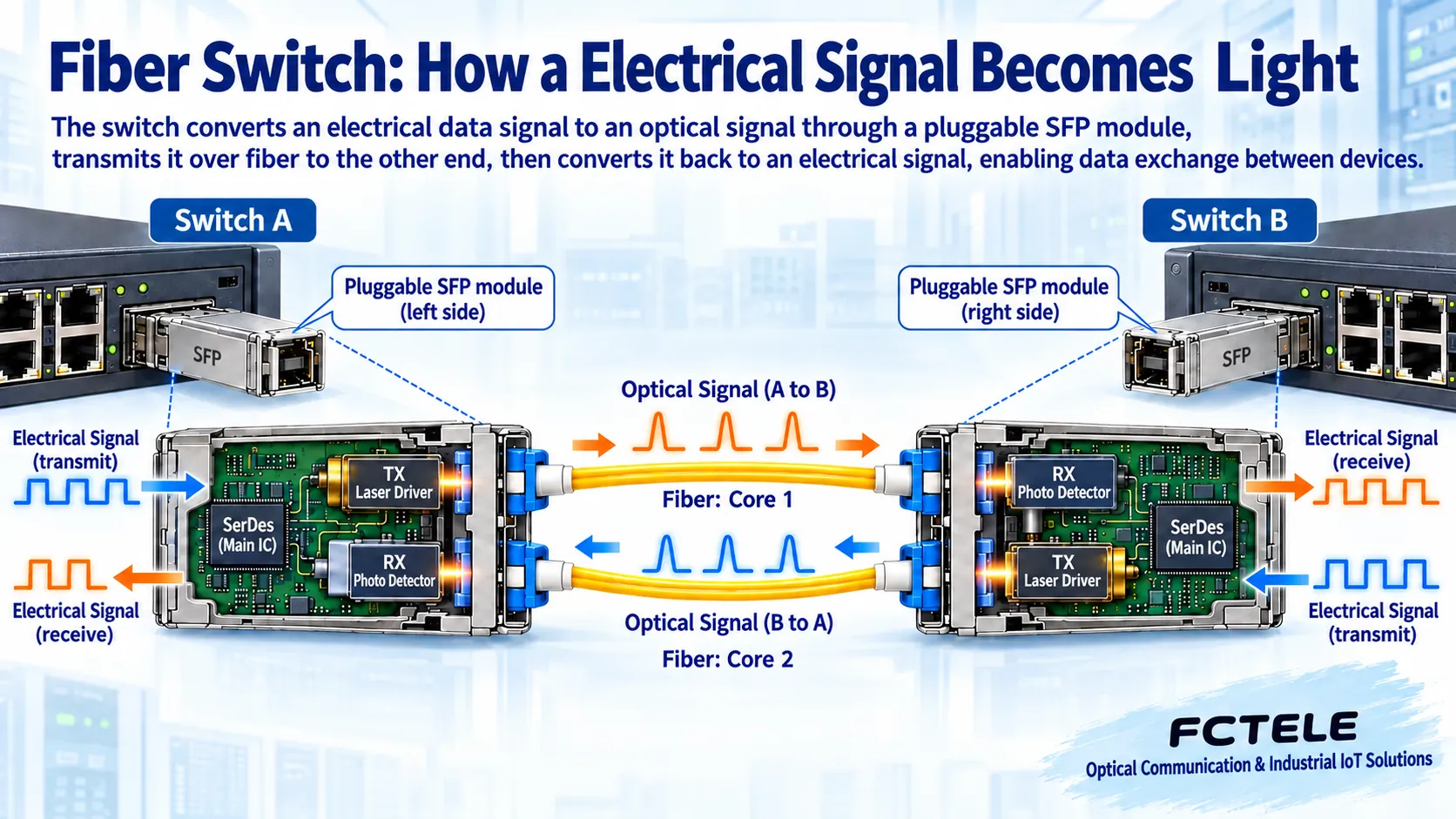
Inside the module, the transmitter converts electrical signals into changes in light, and the receiver detects the light sent from the other end and converts it back into electrical signals. After these conversions, Ethernet frames are still transmitted according to the corresponding link rules; it is not that files are directly turned into images that can fly along the fiber. Inside the switch, the frame address is also used to decide which port to forward from; optical-electrical conversion and switch forwarding work together but are different processes.
2. Why can modules with the same appearance fail to connect?
First, check the speed and module type supported by the device slot. Being able to physically insert it does not prove that the electrical interface, coding, or software support are consistent. Second, confirm single-mode, multimode fiber, and the corresponding optical parameters. The same connector shape does not mean the fiber category or interface polishing type is the same. Mismatched end faces, contamination, or too-tight bending can all cause loss, and you cannot omit checks just because “it is all fiber.”
For a dual-fiber link, each end’s transmitter must connect to the far end’s receiver, and the standards and optical ranges at both ends must be checked. Single-fiber BiDi distinguishes two directions on one fiber core and usually requires complementary transmit and receive wavelength combinations; if both ends choose the same direction model, communication may fail. The procurement list should clearly state the A-end and B-end pairing identifiers, not just write two modules with the same name. Specific wavelengths and speeds must be based on the selected module data and cannot be guessed from a schematic.
3. Rated distance is not a complete link calculation
Light is lost in the fiber core, connectors, and splice points. The optical budget is the allowable loss space between the transmitter’s minimum output and the receiver’s sensitivity under specified conditions. Transmit and receive power are often expressed in dBm, and loss is expressed in dB; the two units have different meanings. Both directions should be calculated separately, and module temperature, aging, and design margin should be considered, rather than just looking at roughly how many kilometers the route is.
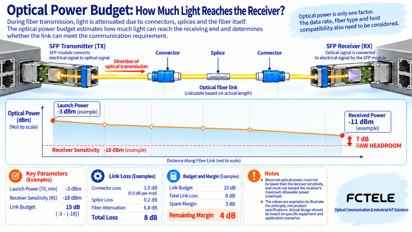
For example, if the minimum transmit power is minus three dBm and the receiver sensitivity is minus eighteen dBm, the difference is fifteen dB. Line loss is eight dB, and after reserving three dB design margin, four dB remains. This example only explains the calculation method and does not indicate that a certain Feichang Technology module has these parameters. Real projects should obtain the selected module’s minimum and maximum transmit power, sensitivity, and overload limit, and recheck with the actual line loss.
Even if the distance is very short, you may not casually choose a long-distance high-power module. If the received light is too strong, it may exceed the overload condition; whether an attenuator is needed should be determined based on the parameters at both ends and actual measurements. On the other hand, sufficient optical power does not automatically prove that all speeds and fiber conditions are compatible; dispersion, standard applicable distance, and host support still need to be checked. The optical budget is one necessary check, not the only pass.
4. Include accessories and installation in the quote scope
At minimum, confirm the number of modules, fiber type, patch cord length, connectors, patch panels, and splicing or connection scope. Switch power supplies, DIN-rail accessories, terminals, and protective grounding materials may also be quoted separately. Laying fiber cable, conduit installation, end-face cleaning, testing, and on-site commissioning should not be ignored during comparison. Some low-price quotes only include the bare unit and empty slots, and only after filling in the rest do you find that it is not the same scope as a complete solution.
For “optical-electrical shared” combo ports, confirm whether the electrical port and the corresponding optical port can be used at the same time. The number of uplinks should also leave room for ring networks, backup, or future expansion, but redundant topologies must have corresponding protocols and configurations; it is not just two fiber cores casually forming a loop. When purchasing, attaching the complete port structure and topology to the quote request is more accurate than separately asking “how much for a few optical and a few electrical ports.”
5. How do environment and maintenance affect cost?
An outdoor line does not mean the switch itself can be exposed to rain. Enclosure protection, cabinets, power supply, and surge protection measures should be designed together according to the actual installation location. Module temperature ratings must also match the device operating conditions; it is not enough for only the switch to be rated for wide temperature while the module is not suitable. The fact that fiber is a non-conductive transmission medium does not mean the entire set of equipment is unaffected by power, copper cabling, or grounding problems, and related protection cannot be omitted.
If digital diagnostic functions are supported, the module can provide some optical power and temperature information, which is helpful for trend troubleshooting, but accuracy, host display, and alarm support should be confirmed by model. Diagnostic readings cannot replace the required on-site testing. Spare parts must be able to pair with the existing host and the far end; single-fiber systems especially should mark the two end models separately; mixing two similar-looking spare parts increases the risk of replacement errors.
6. How to look at Feichang Technology’s optical and electrical port combinations
On the Feichang Technology official website,mini industrial rail-mounted managed 8-gigabit electrical ports plus 1-gigabit optical port series, suitable for aggregating multiple nearby electrical port services onto one optical uplink. Its value is the interface combination and management capability, not “infinite bandwidth just because it has fiber.” The uplink still has a rated speed, and multiple continuous traffic streams must be calculated together; the supplied modules, fiber mode, and compatibility conditions should be clearly stated in the order.
When a project needs multiple optical directions, you can look for other port structures under rail-mounted industrial switch category. Product page titles are for initial screening and do not replace a complete technical agreement. Temperature, optical parameters, whether modules are included with the shipment, and all optional capabilities must be confirmed for the exact configuration. Do not extend the functions supported by one series to all fiber switches.
7. Inquiry and acceptance should follow the same link
Provide the equipment at both ends, speed, fiber core type, route length, number of splice points, installation environment, and power supply conditions, and let the supplier fill in the unit, modules, and accessories separately. Then check taxes, shipping, lead time, warranty, and validity period. Vague price ranges listed by year in old articles are no longer suitable as a procurement basis; this article does not provide unverified current market prices, and actual costs are subject to a valid quote for the same configuration.
On arrival, first check the ordering identifiers at both ends, then clean and connect the end faces according to specifications, and avoid looking directly at an energized optical port. Check link negotiation, module diagnostics, and port errors, and perform bidirectional typical traffic tests; only having the optical port light on does not prove that all services are normal. Archive optical power, configuration, patch cords, and module pairing information so that future troubleshooting can compare item by item. You should not make bends or damage cables yourself to test “resistance.”
Reference note: Optical parameter verification refers to Cisco pluggable optical module installation and specification materials, and specific selection is still subject to the actual host and module manuals. The two figures are general mechanism illustrations; the calculation example in the figure is not a Feichang Technology product measurement or quote.
Translated from the Chinese technical article. Source first published: 2023-10-25. Source last revised: 2026-10-13T17:34:48+08:00. Read the Chinese source
