


An industrial switch case feeling warm is not necessarily a fault; a temperature alarm, repeated disconnections, or reboots also cannot be attributed to heat dissipation by touch alone. On-site troubleshooting must first distinguish where the measurement is taken, then compare environment, load, and communication symptoms on the same timeline. For equipment already affecting production, first restore service according to the on-site plan, then look for the cause under controlled conditions. This article discusses diagnosis of overheating phenomena, and complements the heat dissipation principles article that discusses heat conduction and convection mechanisms.
First answer: where is it hot, and what symptoms occur at the same time
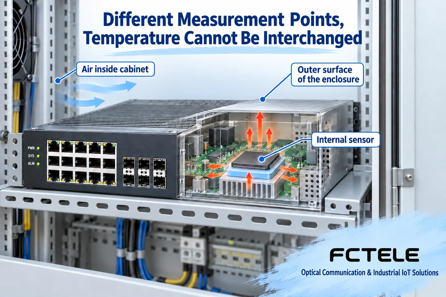
Record the specific model, firmware, power supply, optical module, installation orientation, and recent changes. Replace “very hot” with verifiable information: what was read from the air around the device, the case surface, or the device’s internal sensor, and at what moment it began to change. Different measurement points represent different physical locations; you cannot directly compare case temperature with the ambient temperature limit in the manual, nor treat the CPU temperature shown by software as the air temperature inside the cabinet.
A metal case transfers heat outward and may naturally be warmer than the surrounding air; a warm case sometimes means heat is being expelled, and this alone cannot determine whether chip junction temperature is normal. Conversely, a cool case does not prove there is no local hot spot inside. If there is smoke, a burning smell, abnormal discharge, or a protection action, follow the equipment and site shutdown and isolation procedures, and do not continue applying power for testing; measurements inside the cabinet should be performed by personnel with the appropriate qualifications, and do not open the case or touch parts while it is running.
Align temperature with network counters instead of looking at only one thermal image
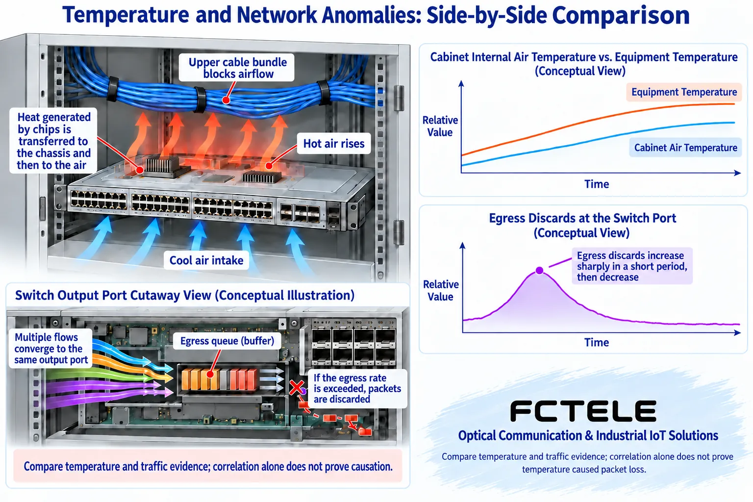
At the same time intervals, record ambient readings, sensor alarms, link changes, port errors, discard counters, and terminal service logs. Counters are often cumulative values, so look at the increment over the same period; if a reboot clears them, note the boundary. Temperature rising before an anomaly is a correlation worth investigating, but it is still not proof of cause. Egress congestion, contaminated fiber, power sags, and ring network changes may also occur at the same time.
An infrared thermal camera sees surface radiation. Metal reflections, emissivity settings, distance, and viewing angle all affect interpretation; in particular, do not use a single reading from a reflective case to infer internal chip temperature. Measurement conditions should be written into the record, and when necessary use a temperature measurement method suitable per the manufacturer’s recommendations. The names, calibration, and alarm thresholds of software sensors must also be checked against the documentation for the corresponding model, and thresholds from another series must not be applied.
Check the cabinet environment first, then check the switch load
Observe the air intake conditions near the device, installation spacing, wiring above it, and nearby power supplies. Outdoor enclosures are affected by sunlight and sealed structures, so the air around the device may differ noticeably from the weather forecast; indoor cabinets can also accumulate heat in a particular location. Do not temporarily remove protective covers or leave cabinet doors open for long periods to cool things down, because this changes dust protection, water protection, and personnel protection conditions. Improving cabinet thermal management must take the original protection requirements into account.
Check whether optical modules, PoE terminals, or high-load services were recently added. The power that PoE outputs to a camera does not all become heat inside the switch chassis, but power conversion and the power supply circuit do have losses. Module temperature ratings, permitted combinations, and the device’s own power consumption should all be verified. Even when Ethernet traffic is low, a switch may still have continuous power consumption from interfaces, power supplies, and modules, so you cannot assume that “no data transmission means no heat.”
Power supply issues should be recorded separately. Input voltage should be checked at the device end and by the specified method when safety conditions permit, observing wiring, terminals, power supply capacity, and protection status. Looking only at a power supply’s no-load output cannot represent conditions under load. For devices with dual power supplies, also confirm that the two paths are independent; connecting two terminals cannot simply be treated as reliable power supply.
Fanless and fan-equipped devices have different troubleshooting paths
For fanless devices, focus on the installation orientation corresponding to the heat conduction path, the space around the case, and air movement; for fan-equipped devices, also check speed alarms, airflow paths, filters, and maintenance intervals. Not all industrial switches have intelligent fans, voice alarms, or online hot-swap capability. Unless the manual authorizes it, do not replace fans while powered, and do not add thermal pads, change control policies, or use external fans to mask a persistent anomaly on your own.
A stopped fan is sometimes a control policy and sometimes a fault, and the judgment must combine thresholds with status information. Do not repeat the general claim that “above a certain fixed power consumption, a fan must be installed”; whether natural cooling is possible is determined jointly by structure, thermal resistance, environment, and verification. Replaceable filters or cleaning areas should be handled according to the maintenance manual; internal cleaning and component repair should be left to technicians, and cabinet dust removal should not be treated as a risk-free online operation.
Change only one condition at a time and keep repeatable evidence
In offline tests or an approved maintenance window, keep other conditions the same and compare installation space, environmental conditions, module combinations, and service load separately. If replacing a device makes things normal, it only means the fault path has been narrowed; it does not prove the original device was necessarily damaged by overheating, because replacing it also changes firmware, configuration, and interfaces. When reproduction is needed, use a controlled load and set stop conditions, and do not repeatedly create disconnections on a production network.
If the anomaly appears only at high temperature, you can further compare port errors, optical module diagnostics, and power supply records; if only egress discards increase while temperature and links are stable, check congestion and queues first. If the symptom disappears after temperature improves, still keep the recovery time and repeated results and give them to the manufacturer to determine whether installation, components, or configuration are involved. Evidence guides repair better than “it seems fine after the device cooled down.”
Selection documentation should become the basis for on-site inspection
Feichang managed industrial six 10-Gigabit optical ports plus 48 gigabit optical/electrical interchangeable Layer 3 switch The public documentation lists case heat dissipation, CPU temperature viewing, system logs, and port statistics. This information can help establish measurement points and network event records, but the specific sensors, commands, and thresholds must still be confirmed according to the delivered version and cannot be generalized to all models. The product page notes that this product has no PoE, so the heat load assumptions of other PoE devices cannot be directly applied to it.
Finally, keep a record containing the model, installation photos, ambient readings, input conditions, load, logs, and handling results. After service is restored, the original protection and backup conditions should still be reviewed and observed according to the actual operating cycle. The goal of diagnosis is to find a verifiable anomaly path, not to draw the same line for all devices with a single temperature number.
Temperature measurement interpretation reference TI thermal measurement note, in which component parameters are not FCTEL equipment specifications.
Translated from the Chinese technical article. Source first published: 2020-09-07. Source last revised: 2026-10-13T18:44:52+08:00. Read the Chinese source
