


Stable converter operation depends on copper physical-layer circuitry, suitable processing, optics, power and clocks working together. One advanced chip cannot explain every performance characteristic, and an internal voltage is not the external supply requirement. Following the signal path helps separate interfaces, optical budgets, thermal conditions and service validation.
Copper Ethernet carries more than simple high/low levels
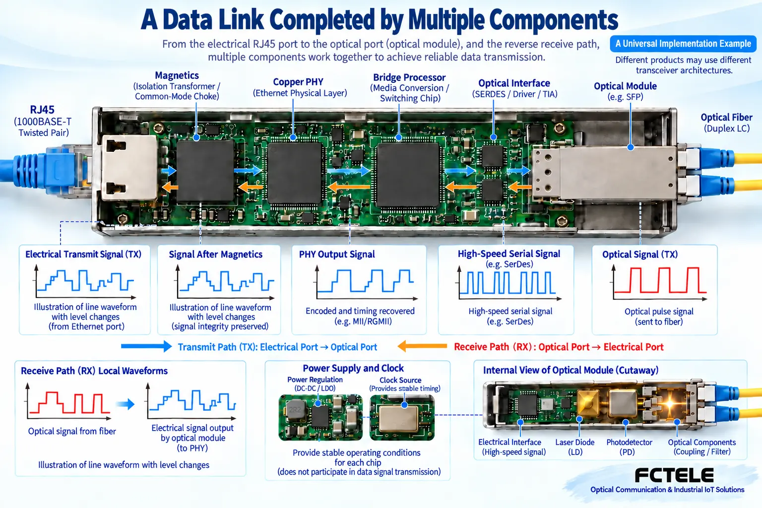
RJ45 connects twisted pairs carrying specified Ethernet signals. Magnetics and interface circuits work with the PHY for suitable coupling and processing. PHY means physical-layer transceiver circuitry: it connects cable signaling to internal data forms rather than directing every network function.
Ethernet rates use different signaling and coding. Real copper waveforms should not all be depicted as a simple voltage square wave. Teaching waveforms can explain mechanisms but must be identified as illustrative. Check PHY speeds, media, modes and operating conditions against chip and complete-device design.
What happens between electrical and optical interfaces?
After copper reception, the implementation delivers data to the optical interface. Some products combine switching chips and optical modules; some PHYs support relevant media-conversion modes. No single architecture describes every converter. Do not claim an internally developed chip without evidence.
TI DP83869HM documentation provides copper/fiber interfaces and conversion modes as one component example. It establishes a possible approach, not that a FCTEL model uses the chip. Actual internal designs need applicable manufacturer evidence, not guesses from port count.
Switching, buffering and address learning have capacity limits. Buffers absorb some bursts, but sustained excess input can still cause drops. Longer-frame support does not imply interpretation or conversion of every protocol. Use complete-device documentation rather than inferring service capability from a PHY name.
Transmission and reception are separate optical processes
A driver controls an emitter to turn data changes into light. A photodetector converts incoming light variations into weak electrical signals for amplification and decisions. Bandwidth, noise, temperature and supply affect performance; port appearance cannot establish these limits.
Duplex links normally use separate cores for directions; BiDi uses complementary wavelengths and internal wavelength separation. Weak receive power may prevent reliable decisions, while excessive light can exceed the operating range. Verify the reverse budget even when one direction works. One LED cannot guarantee bidirectional quality.
Why regulation and clocks matter
External power feeds the unit; internal regulation supplies different components. Main chips, modules and other circuits may use different voltages. An internal rail is not the permitted device input. A board marking cannot replace the unit nameplate or supply specification.
Clocks provide processing timing. Supply or clock faults may cause link drops, errors or resets. Use supported alarms and tests rather than increasing external voltage whenever operation is unstable. Qualified personnel should handle grounding, protection and measurement under manuals and site procedures. Illustrations are not live-disassembly instructions.
Check optical and thermal budgets separately
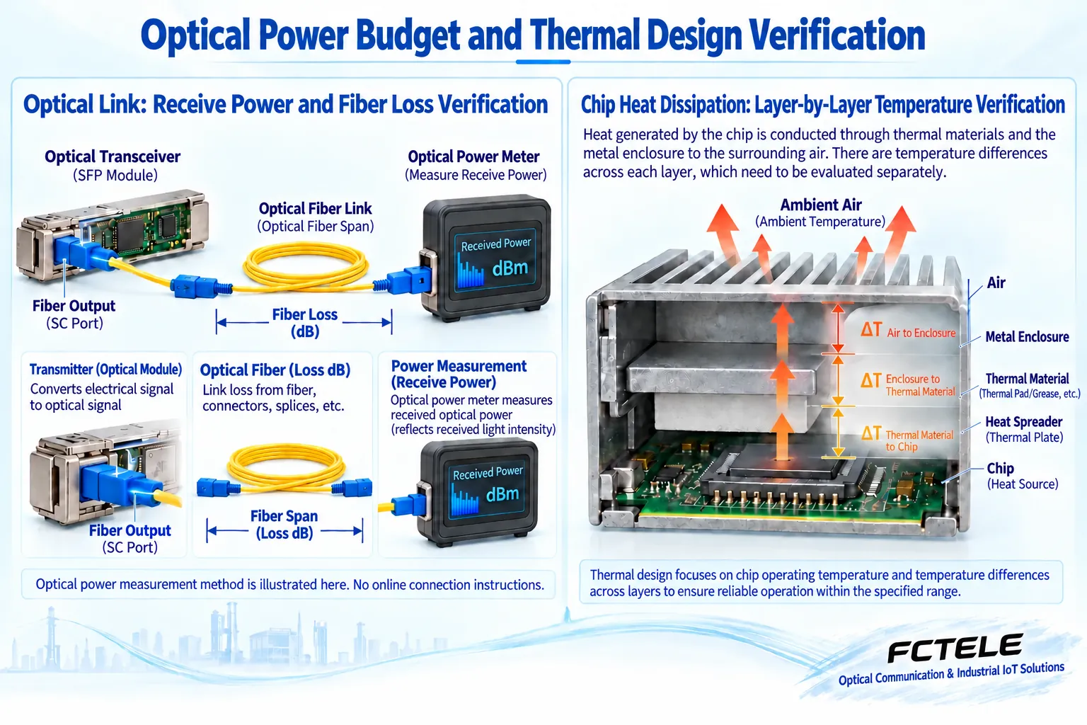
The optical budget concerns whether arriving light stays in the receiver window. Subtract path loss from transmit power, then consider sensitivity, overload and maintenance margin. dBm expresses absolute power relative to a reference; dB expresses ratio or loss. They are different quantities.
The thermal budget concerns removing heat through boards, conductive structures, enclosure and air. Ambient, cabinet and junction temperatures differ. Fanless equipment still generates heat. An enclosure assisting cooling does not permit mounting against another heat source. Verify space and airflow with the specified operating range.
Temperature-tolerant components do not prove unlimited complete-unit environmental capability. Components, connectors, power and enclosure jointly set conditions, which may vary by version. Verify stability under relevant environment and load, not a room-temperature operating photograph.
Management and protection are model-specific
The FCTEL remotely managed Gigabit converter describes switching plus FPGA, OAM and compatible SNMP equipment. That series therefore offers maintenance functions beyond conversion. These are not universal converter features. Confirm companion equipment, firmware and readable/writable items for the order.
Protection claims need specified test conditions. A surge rating cannot promise immunity to every lightning event. Device protection, site grounding, cabling and system protection complement rather than replace one another. Industrial-grade does not automatically mean waterproof, explosion-proof or directly outdoor-installable; check enclosure and certification evidence.
Separate old references to proprietary protocols, chip voltages and unverified in-house development from actual models. Unsupported claims cannot become FCTEL capabilities. Ordinary forwarding must not be described as understanding and converting arbitrary application protocols.
Turn component knowledge into verified complete-unit results
Acceptance has three levels: establishing interfaces/lines, forwarding correctly under normal load, and behaving as designed under specified environments or faults. Confirm rates, optics, fiber and directions first, record power/status/errors next, then observe sustained service and recovery.
With normal power but unstable data, check negotiation, forwarding configuration, peaks and applications. With errors rising as temperature increases, check installation and cooling before declaring a failed laser. Record each change and isolate sections instead of replacing a whole unit on one indicator.
Beginners need not memorize every chip. Remember the path: copper circuitry accepts line signals, processing connects supported data forms, optics emit and detect light, and power/thermal design supports specified conditions. Reliability must be verified in complete equipment and the field rather than inferred from component promotion.
References:TI media-conversion PHY example;FCTEL managed Gigabit converter. Figures explain generic mechanisms, not measurements or model-specific wiring.
Translated from the Chinese technical article. Source first published: 2020-06-08. Source last revised: 2026-10-13T16:02:51+08:00. Read the Chinese source
