


To read converter LEDs, check power first, then optical and copper links separately, and finally speed and duplex.This article explains two six-LED panels by left and right columns. Identical positions need not mean identical functions: the Fast Ethernet upper LEDs separately indicate optical and copper rates; the Gigabit 1000 and 100 LEDs both indicate copper speed. Do not expect every LED to light simultaneously.
1. Data paths and status indicators are different
A fiber media converter extends Ethernet from copper to fiber. The RJ45 PHY, or physical-layer transceiver circuit, recognizes copper signals. Media-conversion circuitry handles corresponding data, and optics convert between electricity and light. Incoming optical data follows the reverse process to Ethernet. Changing media does not turn Ethernet into another service protocol.
Panel LEDs display circuit state; data does not pass through the LEDs. LINK indicates a link and ACT indicates activity, often combined as Link/Act. Steady normally means linked and blinking normally means detected traffic. PWR indicates supply, speed LEDs show the current port rate and FDX indicates full duplex, allowing simultaneous transmission and reception.
These are clues, not proof of application operation. Both links can be lit despite IP, VLAN or application problems. Blink frequency is not a throughput measurement. Hardware can implement configurable LED logic. Match colors and steady/blinking behavior to actual panel markings and the model manual.
2. Fast Ethernet six-LED panel: read the left column, then the right
Figure 1 uses the requested two-column, three-row example. Facing the panel, fiber is left and RJ45 right; the columns are FX and TX. Here TX means twisted-pair copper, unlike TX beside an optical port meaning optical transmit. These traditional panels have no LEDs on RJ45 itself; six indicators form a central array. Do not confuse them with the later B-series RJ45 LEDs. FX/TX label the columns; 100 and Link/Act identify upper/middle rows, with FDX/PWR at the bottom. This layout is an example, not a universal Fast Ethernet rule.
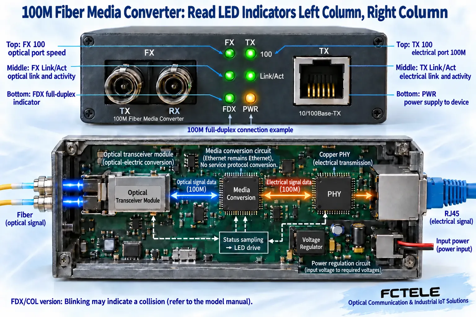
Upper left: FX 100.This indicates the example optical-port Fast Ethernet rate. The 100 marking does not prove fiber connectivity; also check the middle-left LED. Fixed-rate models may omit a speed LED or use different names. Do not infer meaning from position alone.
Middle left: FX Link/Act.This indicates optical link/activity. Steady normally means linked; blinking normally means optical traffic. If dark, check peer power, single-/dual-fiber pairing and optical/module rates, then core connections and loss. Duplex local TX connects to remote RX in each direction.
Lower left: FDX.In this example it indicates duplex. On commonly means full duplex; check the model for off-state meaning. With FDX/COL markings, COL means collision and blinking may indicate half-duplex collisions. Do not universally equate on or blinking with full duplex. If copper settings differ, check negotiation and errors rather than relying on this LED.
Upper right: TX 100.This indicates copper operation at 100 Mbps. On a 10/100 model with an established copper link, off may mean 10 Mbps. It can also be off when disconnected, so evaluate it with the middle-right LED.
Middle right: TX Link/Act.This indicates RJ45 link/activity. If off, check peer power and cable seating, then compare known-good cables and ports. On/blinking confirms only the relevant link/activity, not reachability of a remote server.
Lower right: PWR.This indicates supply. On does not prove every internal circuit works. If off, first check plug, adapter and rated input. Verify voltage, polarity and current capacity before substitution; a fitting plug is insufficient. Do not open a live enclosure.
3. Gigabit six-LED panel: same columns, different upper indicators
Figure 2 keeps the same reading order. Crucially, 1000 and 100 both indicate example copper speed, rather than separate copper/optical speeds. Confirm Gigabit optics through specifications and FX Link/Act. Upper-left 1000 is not proof that the optical Gigabit link works.
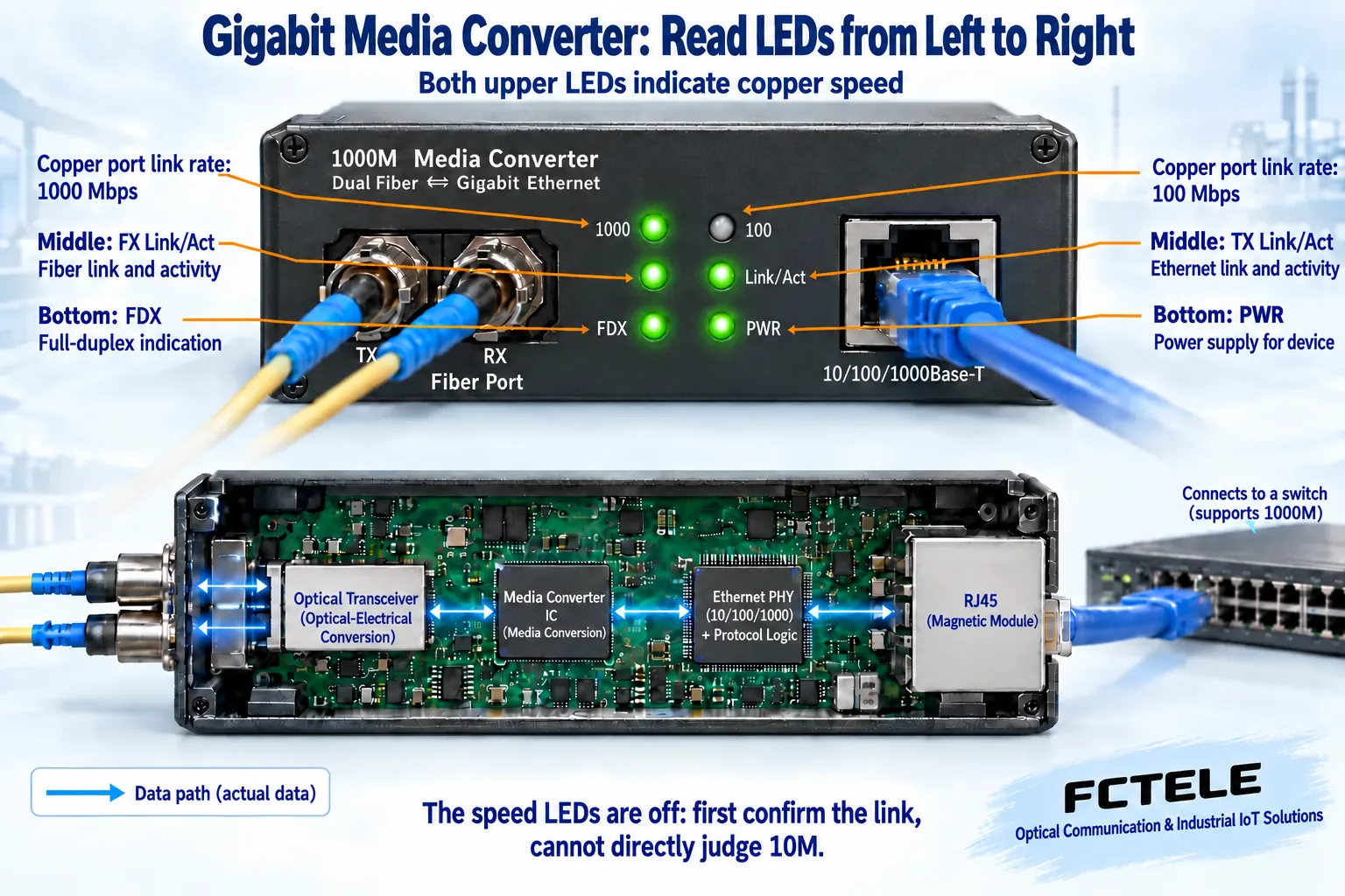
Upper left: 1000.Here on means copper negotiated 1000 Mbps. It does not prove Gigabit application throughput or Gigabit service at the far end.Middle left: FX Link/Act.Still indicates optical link/activity.Lower left: FDX.Still follows model duplex definitions; check any COL function separately.
Upper right: 100.Here on means copper negotiated 100 Mbps, another copper-rate indication like upper-left 1000.Middle right: TX Link/Act.Still indicates RJ45 link/activity.Lower right: PWR.Still indicates supply. Keeping the same column order avoids switching between column and row reading methods.
If 1000 and 100 are both off, check TX Link/Act first. Both speed LEDs being dark is normal with no copper link. Infer 10 Mbps only if the model supports it and the manual speed combinations and link state confirm it. Some Gigabit devices support only particular copper/optical rates.
For example, a Gigabit converter connected to a Fast Ethernet camera may normally show upper-right 100 on, upper-left 1000 off and middle-right activity blinking. This is not necessarily a fault. If a Gigabit switch still negotiates 100 Mbps, check capabilities, settings and cable. Gigabit copper needs all four pairs; a bad contact can cause fallback or instability.
4. FCTEL B-series: follow actual markings, not a forced six-LED template
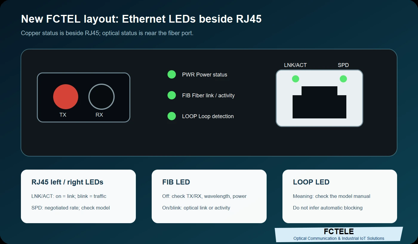
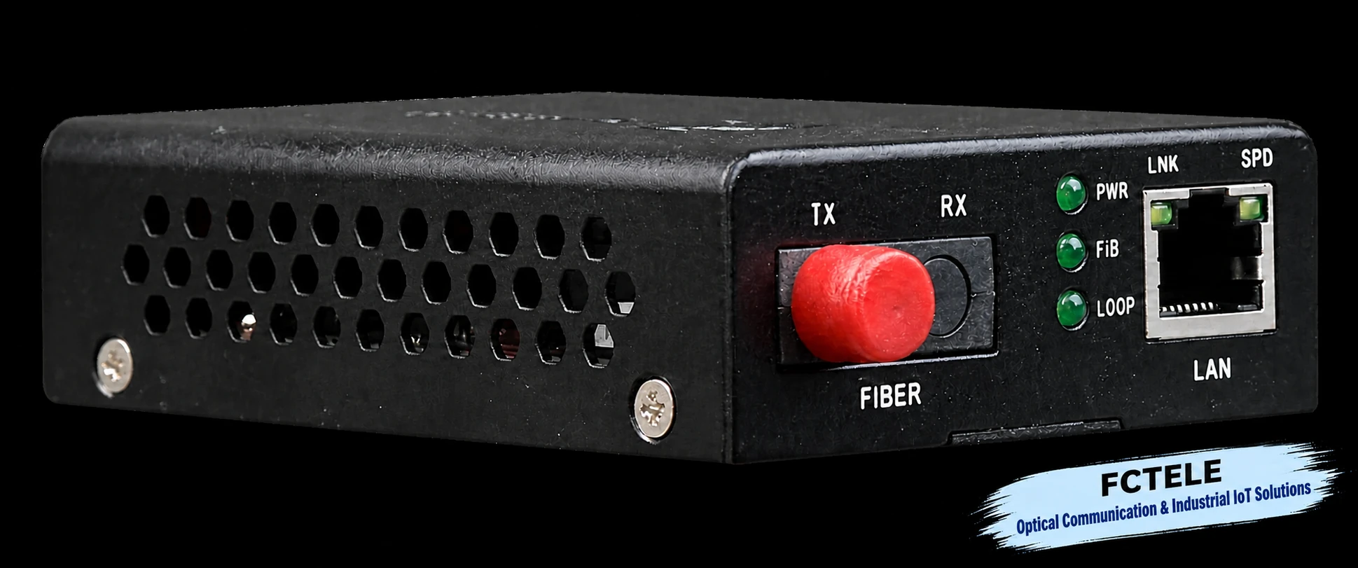
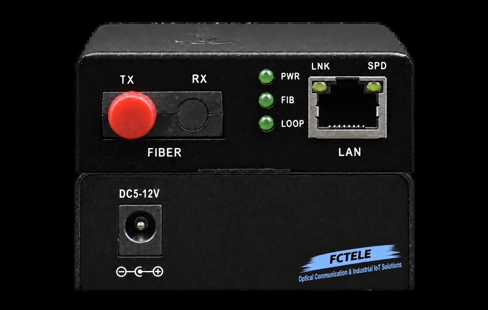
The official B-series Gigabit photograph shows PWR, FIB and LOOP near the optics and LNK/SPD beside RJ45. For copper, look beside RJ45; for fiber, look at FIB. LNK indicates link and SPD speed, with colors/blink patterns confirmed by ordered version. A LOOP marking alone cannot establish automatic blocking, alarm methods or universal trigger conditions.
Published options include adaptive copper and several optical configurations for extending Ethernet over fiber. Verify copper rates and optical configuration separately; copper adaptation does not imply arbitrary optical rate conversion. Confirm inconsistent rate descriptions against the exact ordered model. This article does not invent alarm behavior from a photograph.
For comparison with the actual unit, see B-series single-port Gigabit details and panel photographs; for Fast Ethernet, see B-series single-port Fast Ethernet documentation. Identify the model before applying this reading method.
5. Move from LEDs to segment-by-segment fault verification
Photograph both panels before changes, noting labels, steady/blinking states and peers. Check PWR, then optics. With no optical link, verify TX/RX, fiber count and compatible modules. Single-fiber equipment needs complementary configurations, not two arbitrary identical units. Never look into ports; use suitable cleaning and measurement tools.
Then check RJ45. Change one known-good cable or port at a time and record status changes to separate cable, peer and converter faults. Investigate negotiation and cable before forcing Gigabit. If one failure makes another LED go dark, check enabled link-fault propagation rather than assuming two simultaneous hardware faults.
When both optical and copper links appear normal but service fails, investigate switch statistics, MAC learning, VLAN, IP and applications. Verify local-network communication before gateways and remote services. LEDs begin diagnosis; acceptance needs actual traffic, errors and sustained observation, not all lights on.
References and illustration notes:Panel explanations apply to the illustrated six-LED examples. Circuits are generic mechanisms, not FCTEL teardowns, measurements or specifications. Configurable LED behavior and duplex/collision distinctions refer to the TI DP83848C datasheet LED section; selection refers to the FCTEL pages above. Chip documentation explains mechanisms, not evidence of that chip in a FCTEL product. Actual positions, colors, blinking, rates and functions follow the model manual and markings.
Translated from the Chinese technical article. Source first published: 2020-03-05. Source last revised: 2026-10-13T16:02:51+08:00. Read the Chinese source
